Method and System for 2D Detection of Localized Light Contributions

a localized light and detection method technology, applied in the field of illumination systems and optical receivers, can solve the problems of high acquisition rate, inability to detect embedded codes present at single positions, and use of advanced and expensive cameras capable of providing high acquisition rate, so as to achieve less expensive effects

Inactive Publication Date: 2012-11-08
KONINKLIJKE PHILIPS ELECTRONICS NV
View PDF13 Cites 39 Cited by
  • Summary
  • Abstract
  • Description
  • Claims
  • Application Information

AI Technical Summary

Benefits of technology

[0008]It is an object of the invention to provide a detection system and a method capable of detecting 2D CL embedded into a light output of light sources in a manner that allows identification of the embedded codes of the different light sources being present in a 2D scene. It is a further object of the invention to provide a detection system and method suitable for detecting the invisible “high frequency” CL while using less expensive cameras as those used in the previous techniques.

Problems solved by technology

A drawback of the previous CL detection techniques is that only embedded codes present at single positions can be detected.
However, a drawback of the previous techniques employing camera sensors is that the acquisition time of the sensor must be equal to the duration of a single bit within the embedded code.
When CL is embedded in a manner that is invisible to a human eye (i.e., embedded at high frequency), such techniques require the use of advanced and, therefore, expensive cameras capable of providing high acquisition rate.
Conventional low-cost camera sensors typically have too low of an acquisition rate to detect such high frequency CL.
Therefore, currently, the only methods for CL detection that can work with conventional low-cost cameras require the identifiers to be embedded in such a manner that the CL modulation cannot be completely invisible because the viewers can visually perceive the low frequency modulation as flickering in the light.

Method used


Image

  • Method and System for 2D Detection of Localized Light Contributions
  • Method and System for 2D Detection of Localized Light Contributions
  • Method and System for 2D Detection of Localized Light Contributions

Examples


Embodiment Construction

[0046]In the following description, numerous specific details are set forth to provide a more thorough understanding of the present invention. However, it will be apparent to one of skill in the art that the present invention may be practiced without one or more of these specific details. In other instances, well-known features have not been described in order to avoid obscuring the present invention.

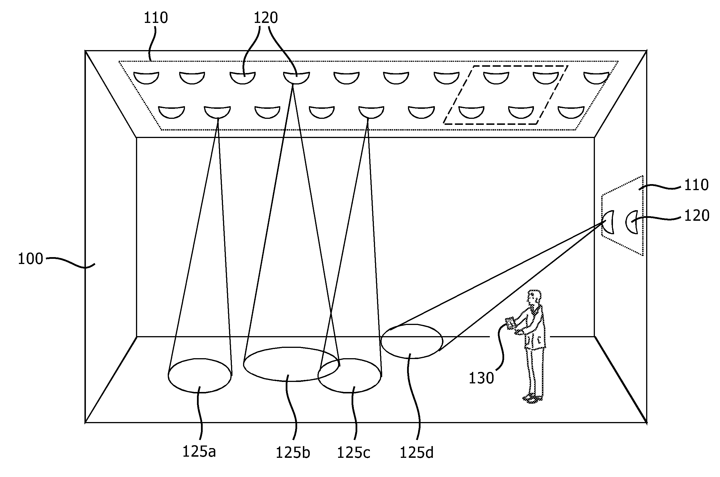
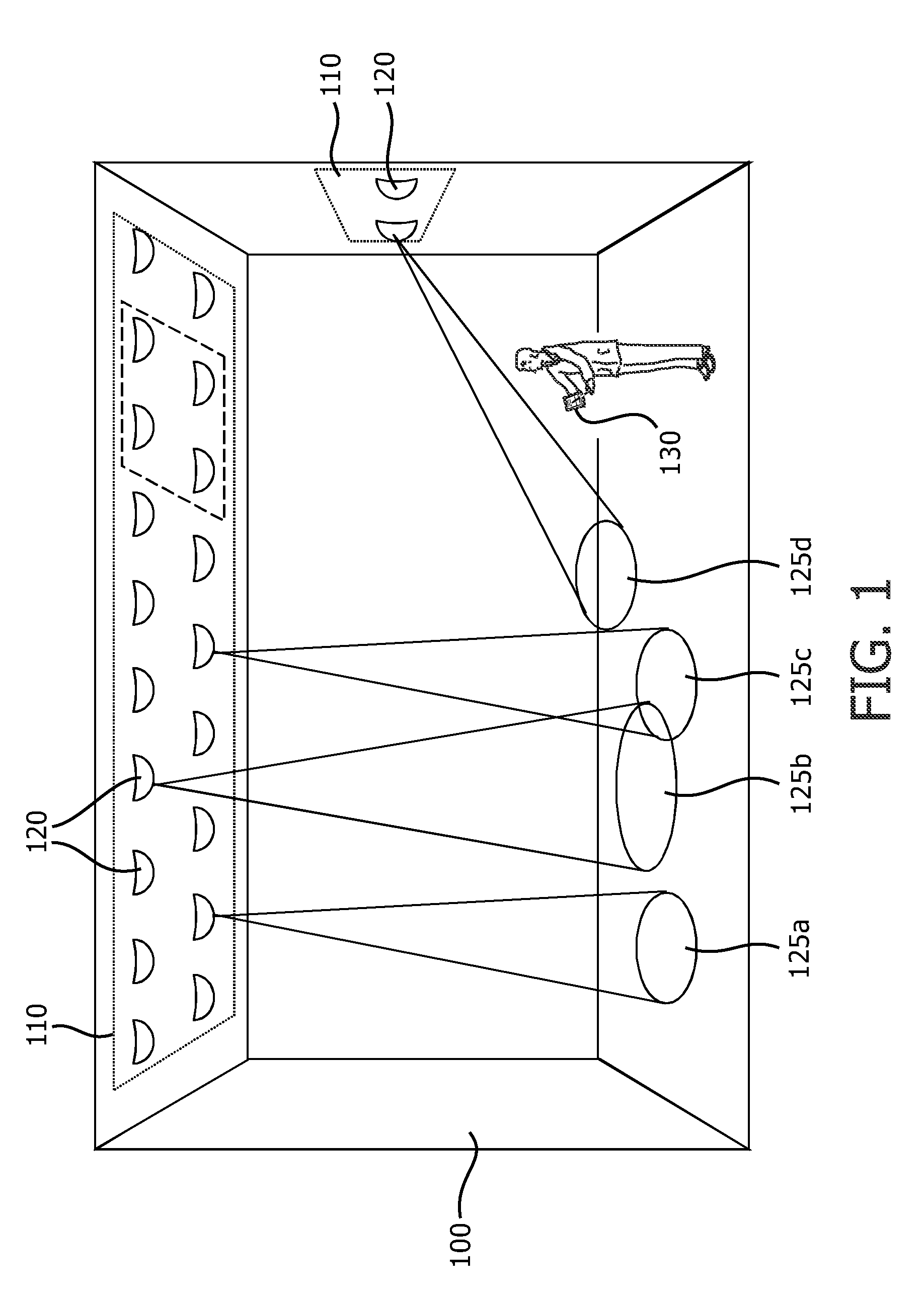
[0047]FIG. 1 shows a structure 100—in this case a room—with an installed illumination system 110. The illumination system 110 comprises one or more of light sources 120 and one or more controllers (not shown in FIG. 1) controlling the light sources 120. When driven with an electrical signal, the light sources 120 illuminate parts of the structure 100, the illumination contributions from the various light sources 120 shown as footprints 125a-125d. The light sources 120 may comprise high / low pressure gas discharge sources, inorganic / organic light emitting diodes, laser diodes, incandescen...


PUM


Abstract

The invention relates to a detection system for determining whether a light contribution of a light source is present at a selected position within a 2D scene. The light contribution includes an embedded code comprising a repeating sequence of N symbols. The detection system includes a camera and a processing unit. The camera is configured to acquire a series of images of the scene via specific open/closure patterns of the shutter. Each image includes a plurality of pixels, each pixel representing an intensity of the light output of the light source at a different physical position within the scene. The processing unit is configured to process the acquired series of images to determine whether the light contribution of the first light source is present at the selected physical position within the scene by e.g. correlating a sequence of pixels of the acquired series corresponding to the selected physical position with the first sequence of N symbols.

Description

FIELD OF THE INVENTION[0001]Embodiments of the present invention relate generally to the field of illumination systems and optical receivers, and, more specifically, to systems and methods for detecting data embedded into the light output of such illumination systems.BACKGROUND OF THE INVENTION[0002]In recent years, highly advanced illumination systems are being developed that allow consumers to obtain a desired ambiance for a particular room or space. These illumination systems move away from the traditional control of individual light sources (switching on / off and dimming) towards scene setting, where sets of light sources are controlled simultaneously. An example of such an illumination system is an arrangement of several sets of light sources in a room, a lobby, or a vehicle.[0003]For these scene setting applications, intuitive user interaction is identified as one of the most important success factors. Providing a user with information related to the light sources, such as loca...

Claims


Application Information

Patent Timeline
Patent Type & Authority Applications(United States)
IPC IPC(8): G06K9/46H04N7/18G06V10/145
CPCH05B37/02G06K9/2036H05B47/165H05B47/17G06V10/145
Inventor VLUTTERS, RUUDDE BRUIJN, FREDERIK JANFERI, LORENZOSCHENK, TIM CORNEEL WILHELMUSMUIJS, REMCO THEODORUS JOHANNES
Owner KONINKLIJKE PHILIPS ELECTRONICS NV
Why Eureka
Try Eureka