
Moveable Element and Power Generation System for Low Head Facilities

a technology of moving elements and power generation systems, applied in water power plants, conventional hydroenergy generation, coastline protection, etc., can solve problems such as large gross head pressure, undesirable fixed water flow path, and inability to move downstream water

Active Publication Date: 2012-11-08
HYDRO GREEN ENERGY LLC
View PDF7 Cites 1 Cited by
  • Summary
  • Abstract
  • Description
  • Claims
  • Application Information

AI Technical Summary

Benefits of technology

[0009]Another advantage of the present invention is to provide a system for converting low head dams into hydropower facilities while providing minimal interference with water flow during floods.
[0011]Another advantage of the present invention is to provide a system that uses a hydropower turbine attached to a movable element that increases available gross head pressure.

Problems solved by technology

Accordingly, anything fixed in the flow path of the water that might interfere with downstream water movement is undesirable to them.
These systems, however, are not intended for power generation, but to increase the height of the blocked water in the upper pool, thereby creating a larger gross head pressure.
However, none of these systems allow for the situational use of hydropower in a deployable system that may be placed in virtually any environment where low head is available while at the same time having the ability to let water pass over the turbine powerhouse during flooding events so that the turbine powerhouse does not reduce the flow of flood waters on the dam or dam spillway.
Nor do any of these systems allow for a variety of combinations of turbines and movable walls to create interchangeable power generating cells and enhancements.

Method used


Image

  • Moveable Element and Power Generation System for Low Head Facilities
  • Moveable Element and Power Generation System for Low Head Facilities
  • Moveable Element and Power Generation System for Low Head Facilities

Examples


Embodiment Construction

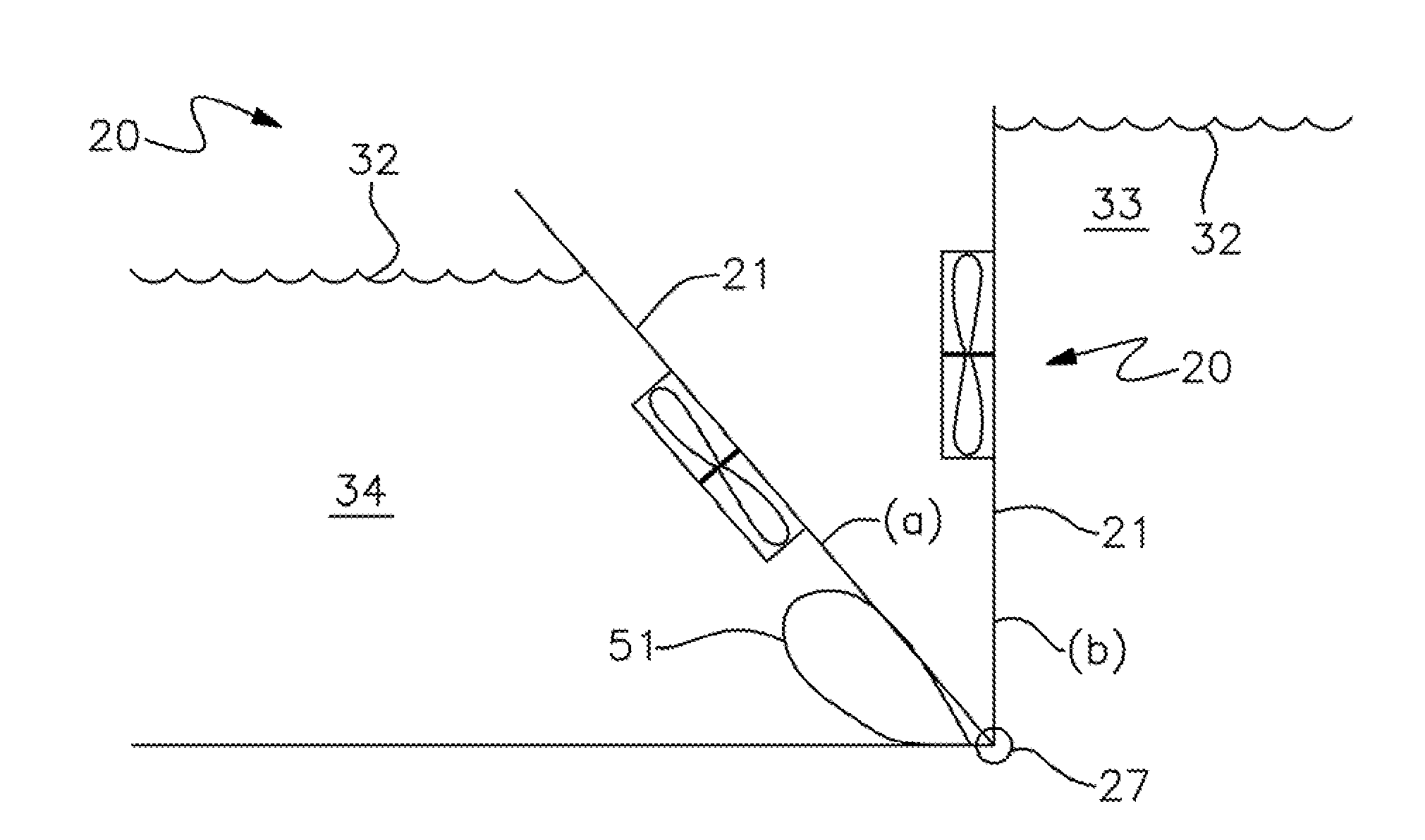
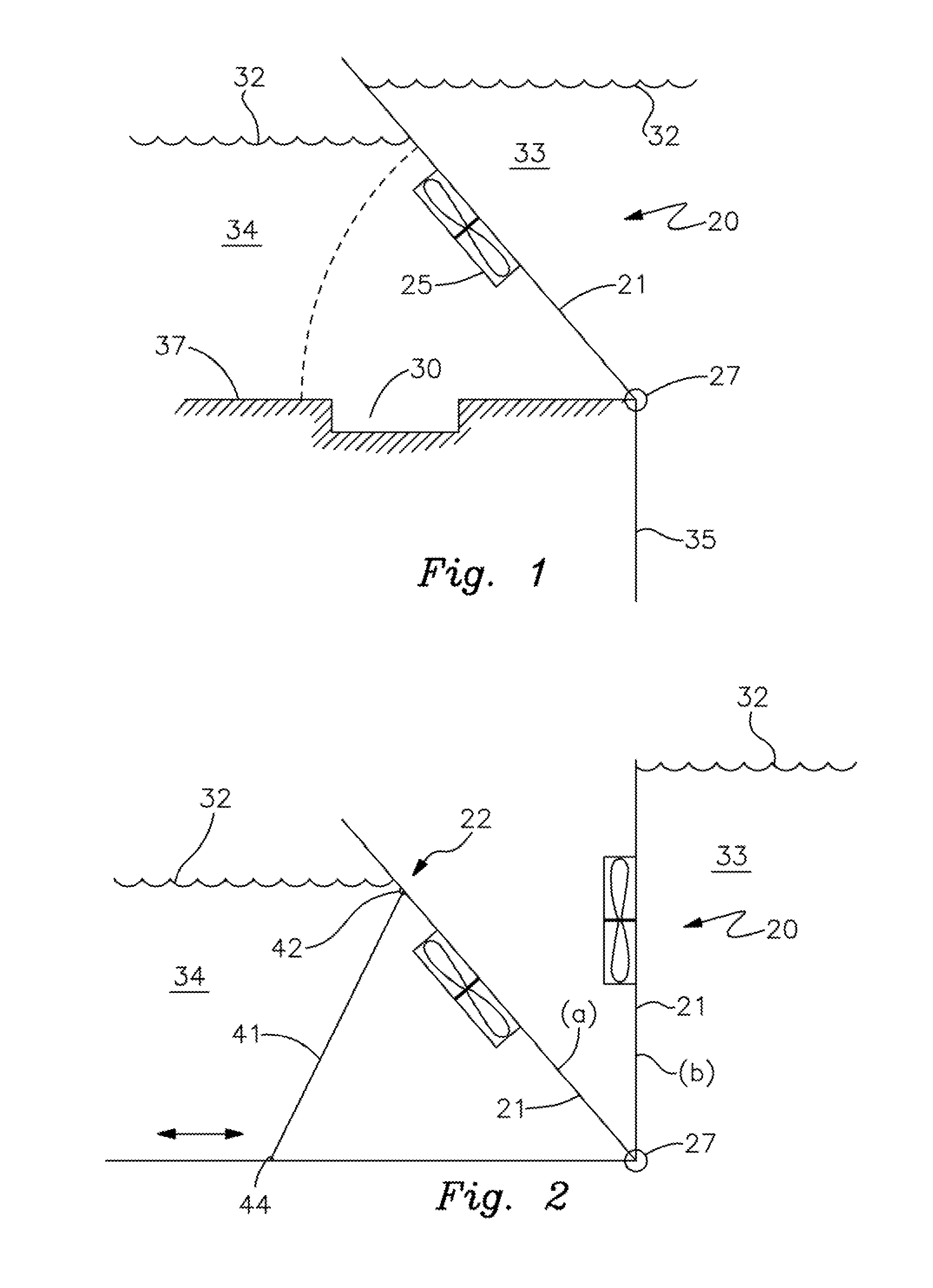
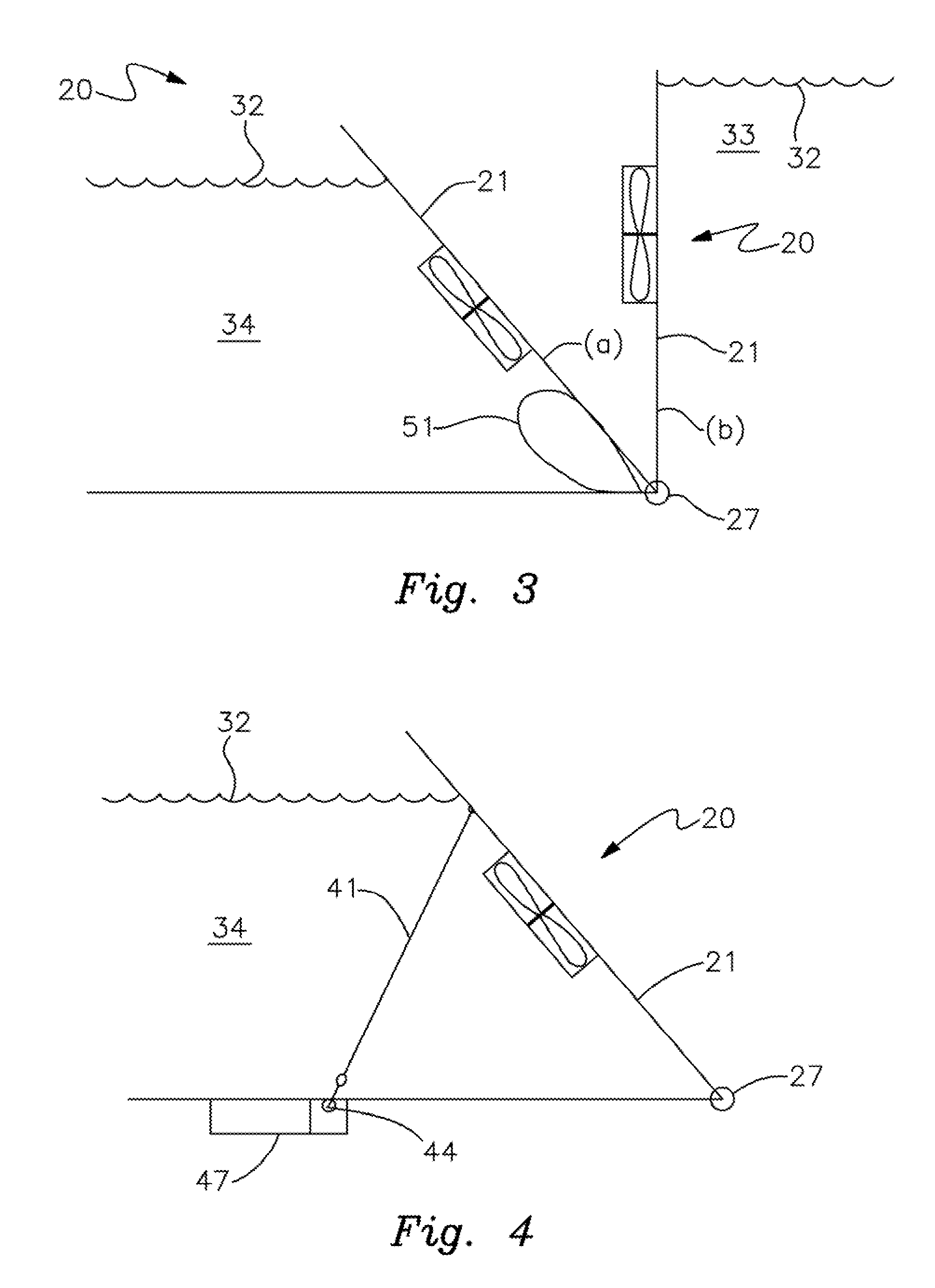
[0024]Detailed descriptions of the preferred embodiments are provided herein. It is to be understood, however, that the present invention may be embodied in various forms. Various aspects of the invention may be inverted, or changed in reference to specific part shape and detail, part location, or part composition. Therefore, specific details disclosed herein are not to be interpreted as limiting, but rather as a basis for the claims and as a representative basis for teaching one skilled in the art to employ the present invention in virtually any appropriately detailed system, structure or manner.

[0025]Turning first to FIG. 1, there is shown a wall 21 having an integrated, interchangeable turbine and generator combination 25 disposed in wall 21 to create a power generating cell 20. Cell 20 may be placed on the side of wall 21 or, in some embodiments, disposed completely flush into the wall. As illustrated more closely in the embodiment shown in FIGS. 1, 2 and 3, one end of wall 21 i...


PUM


Abstract

A low head power generating system is disclosed including a wall pivotably attachable to a structure for moving between a generally upright position and a generally flat position. In the upright position, the structure or wall impounds water, and has a power generating cell connected to the wall, which rotates by movement of water there-through and is operably connectable to a generator for generating power. A support braces the wall in the upright position. The support is adjustable with a first end connected to the wall and a second end extended against a structure, and can be an inflatable bladder, a pressurized piston or other mechanism to move the wall. The cell can be mounted on the surface of the wall or integrated within the wall.

Description

CROSS REFERENCE TO RELATED APPLICATIONS[0001]This application claims priority to U.S. Provisional Patent Application No. 61 / 482,256 filed May 4, 2011, which is incorporated as if fully set forth herein.BACKGROUND OF THE INVENTION[0002]1. Field of the Invention[0003]This invention relates to low head hydropower facilities, and more particularly to a moveable element and power generation system for low head facilities.[0004]2. Description of Related Art[0005]Of the approximately 80,000 dams in the United States, about 2,500 of them produce some electricity. There is, therefore, a large inventory of non-hydropower producing dams. At these dams, water is released either continuously, or on an intermittent to regular basis for, among other things, flood control or irrigation purposes. Usually, governments and municipalities do not want anything to interfere with releasing water from the dams or reservoirs, or interfere with water movement downstream. Accordingly, anything fixed in the fl...

Claims


Application Information

Patent Timeline
Patent Type & Authority Applications(United States)
IPC IPC(8): E02B9/00
CPCE02B7/40Y02E10/22E02B9/022Y02E10/20
Inventor KROUSE, WAYNE F.
Owner HYDRO GREEN ENERGY LLC
Learn More