Catalyst for converting exhaust gases

a technology of catalyst and exhaust gas, which is applied in the direction of physical/chemical process catalyst, metal/metal-oxide/metal-hydroxide catalyst, and separation process, etc. it can solve the problems of increasing the material cost of catalyst, affecting the warm-up performance of catalyst, and not at all disposed of catalytic layers at proper parts or regions. , to achieve the effect of higher conversion performan

Active Publication Date: 2012-11-08
TOYOTA JIDOSHA KK +1
View PDF1 Cites 20 Cited by
  • Summary
  • Abstract
  • Description
  • Claims
  • Application Information

AI Technical Summary

Benefits of technology

[0012]The present invention has been developed in view of such circumstances. It is therefore an object of the-present invention to provide a catalyst for converting exhaust gases, catalyst which can demonstrate the conversion characteristics of catalytic ingredients fully, and which exhibits higher conversion performance at low temperatures.

Problems solved by technology

However, in all of the catalysts for converting exhaust gases that are disclosed in the aforementioned three patent publication gazettes, the catalytic layers are not at all disposed at proper parts or regions in the substrate after fully considering the respective conversion characteristics of the catalytic noble metals.
However, augmenting the loading amount has resulted in raising the material cost of catalyst.
In addition, the warm-up performance of catalyst is affected by the activity of catalytic noble metal being loaded on the upstream section and how likely it is that the catalyst is warmed up, namely, the catalyst's heat capacity.
Moreover, in the zone coated catalysts, the more downstream side the downstream-side catalytic layer is disposed the more susceptible it is to the poisoning by sulfur, and degraded atmospheres.

Method used


Image

  • Catalyst for converting exhaust gases
  • Catalyst for converting exhaust gases
  • Catalyst for converting exhaust gases

Examples


example no.1

EXAMPLE NO. 1

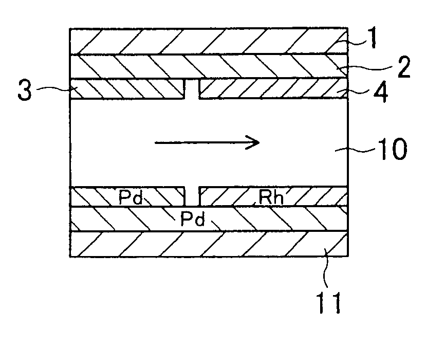
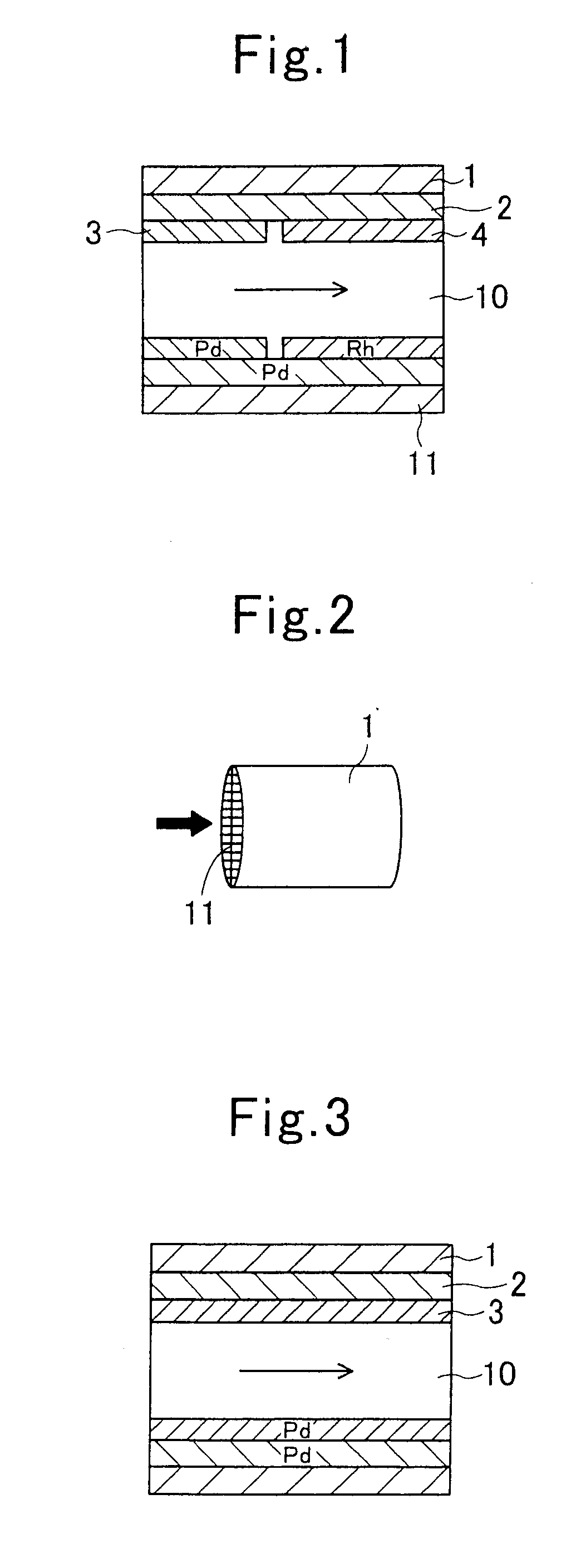
[0089]As illustrated in FIG. 1, a catalyst for converting exhaust gases according Example No. 1 of the present invention comprised a substrate 1, and a catalytic layer 10. The catalytic layer 10 was formed on the substrate 1, and comprised a lower catalytic layer 2, a first upper catalytic layer 3 and a second upper catalytic layer 4. The lower catalytic layer 2 was formed on the face of the substrate 1 directly. The first upper catalytic layer 3 was formed on an upstream-side section in the face of the lower catalytic layer 2. The second upper catalytic layer 4 was formed on a downstream-side section in the face of the lower catalytic layer 2.

[0090]As illustrated in FIG. 2, the substrate 1 was a monolithic substrate that was made of cordierite and had a honeycomb structure. Moreover, the substrate 1 had a circular cross section whose diameter was 103 mm, had an overall length of 105 mm, and had a whole volume of 875 c.c. In addition, the substrate 1 comprised cellular ...

example no.2

EXAMPLE NO. 2

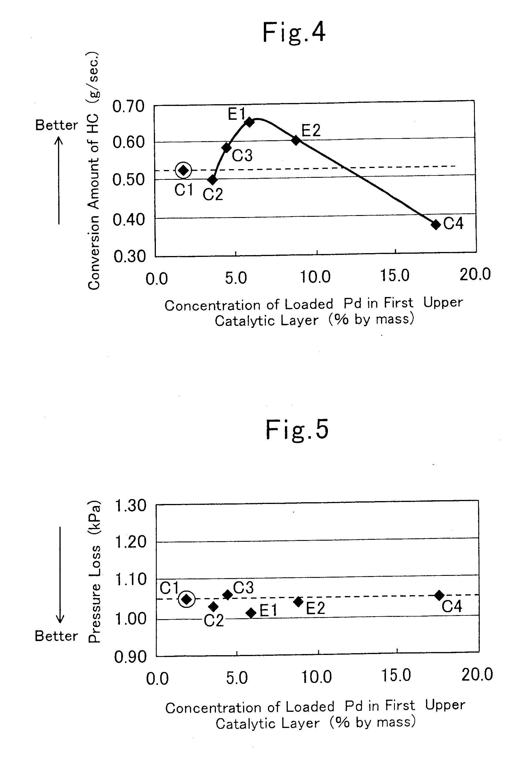
[0098]A catalyst for converting exhaust gases according to Example No. 2 of the present invention comprised a first upper catalytic layer 3 in which loaded Pd accounted for 8.8% by mass of the first upper catalytic layer 3′ whole mass being taken as 100% by mass. Moreover, the first upper catalytic layer 3 was formed in an exact or absolute coating amount of 20 g (i.e., 22.9 g per 1-liter substrate). In addition, the first upper catalytic layer 3 had a length of 21 mm. In other words, the catalyst according to Example No. 2 comprised a first upper catalytic layer 3 in which Pd was loaded in the same amount as that in the first upper catalytic layer 3 of the catalyst according to Example No. 1, and which was formed in a reduced coating amount that was less than that in the first upper catalytic layer 3 of the catalyst according to Example No. 1. As a result, in the catalyst according to Example No. 2, not only the first upper catalytic layer 3 exhibited an increased conc...


PUM

PropertyMeasurementUnit
temperaturesaaaaaaaaaa
operating temperaturesaaaaaaaaaa
volumesaaaaaaaaaa

Abstract

A catalyst for purifying exhaust gases includes a substrate, and a catalytic layer. The catalytic layer includes a lower catalytic layer, a first upper catalytic layer, and a second upper catalytic layer. The lower catalytic layer being loaded with Pd and / or Pt is formed on the substrate. The first upper catalytic layer being loaded with Pd covers an upstream side of the lower catalytic layer, and exhibits a concentration of loaded Pd that falls in a range of from 4.5 to 12% by mass when the entirety of the first upper catalytic layer is taken as 100% by mass. The second upper catalytic layer being loaded with Rh covers a downstream side of the lower catalytic layer.

Description

DESCRIPTION[0001]1. Technical Field[0002]The present invention relates to a catalyst for purifying exhaust gases. In particular, it relates to a catalyst for purifying exhaust gases that comprises an upstream side and a downstream side, on which different species of catalytic ingredients are loaded respectively, in the flow passage of exhaust gases.[0003]2. Background Art[0004]A catalyst for converting exhaust gases, which converts exhaust gases that are emitted from an automotive engine, is provided with a catalytic layer on the surface of a substrate. The catalytic layer comprises a catalytic ingredient, such as Pt, Pd and Rh, and a support for loading the catalytic ingredient thereon. The catalytic ingredient and support exhibit different functions depending on the respective components. Accordingly, while taking the facts that the temperature and exhaust-gas components show gradients between the respective parts or regions in catalyst into consideration, the following catalysts ...

Claims


Application Information

Patent Timeline
Patent Type & Authority Applications(United States)
IPC IPC(8): B01J23/46B01J21/04
CPCB01D53/945Y02T10/22B01D2255/1025B01D2255/9022B01J23/002B01J23/63B01J35/0006B01J35/002B01J35/04B01J37/0009B01J37/0244B01J37/0248B01J37/031B01J2523/00B01D2255/1023B01J2523/31B01J2523/3706B01J2523/3712B01J2523/48B01J2523/3718B01J2523/36Y02T10/12
Inventor SUNADA, TOMOAKIUENO, HIDEAKIAOKI, YUKIYOSHIDA, TAKERUNAKAHARA, MASAHIROKAWAI, MASAAKISAKAGAMI, SINGO
Owner TOYOTA JIDOSHA KK
Why Eureka
Try Eureka