Self-reinflating tire

a self-inflating, tire technology, applied in the direction of generator/motor, heavy duty tyres, cycles, etc., can solve the problems of excessive and achieve the effect of increasing purchase costs and complexity of the device itsel

Active Publication Date: 2012-11-15
CODA INNOVATIONS SRO
View PDF3 Cites 16 Cited by
  • Summary
  • Abstract
  • Description
  • Claims
  • Application Information

AI Technical Summary

Benefits of technology

[0002]Different solutions for maintenance of pressure in the tire under operation are used in technical practice. For example, it is a tire provided

Problems solved by technology

Drawbacks of these solutions are extensive purc

Method used


Image

  • Self-reinflating tire
  • Self-reinflating tire
  • Self-reinflating tire

Examples


example 1

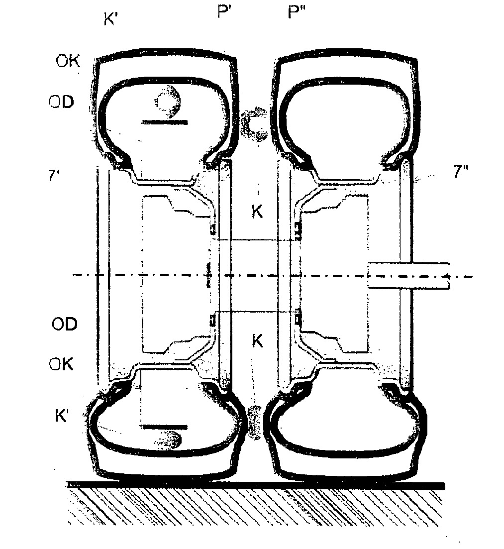
[0022]The chamber 1 for adjustment of pressure in the tire P is created inside the tire P alongside at its tread part in the space defined by the wall of the tire P from the top and by at least a part of the ring OK from the bottom with its length defined in such a way that an unloaded part of the ring OK is away from the wall of the tire P. It means if the wall of the tire P lies, for example, on the radius of 50 cm and the ring OK on the radius of 49 cm there will be a 1 cm high space between them. Such a space between the ring OK and the wall of the tire P will be thereinafter called PO. A chamber K can be placed within this space PO. A loaded tire P bears against the chamber K in the point of load deformation and closes it crosswise under the condition that the deformation of the tire P overcomes the whole cross-section of the chamber K. This allows the right function of the chamber K for the inflation of the tire P; the place of closure moves along the chamber K and pumps the a...

example 2

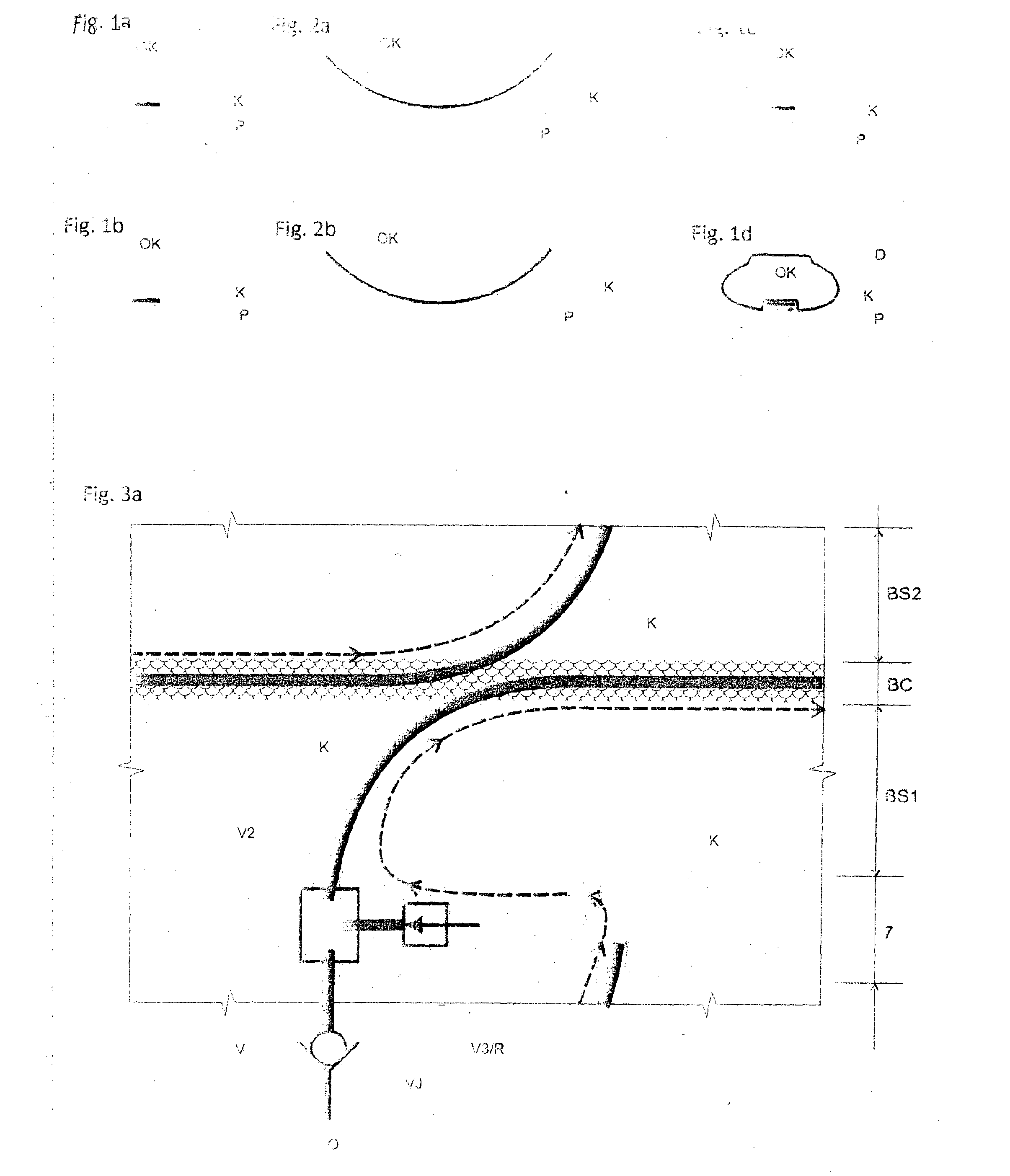
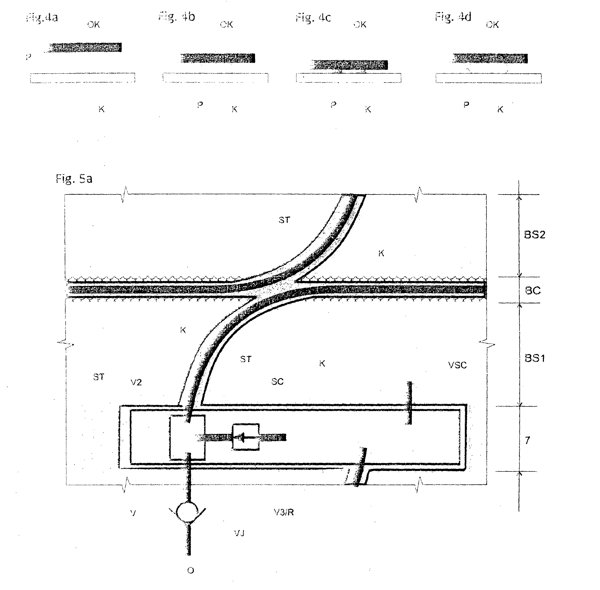
[0023]FIG. 1 shows a section through an non-deformed tire P, ring OK placed near the inner tread part of the tire P and chamber K placed between the ring OK and the wall of the tire P. FIG. 1b shows the tire P deformed and chamber K closed crosswise. While the chamber K on FIG. 1a is placed within the space PO and at its side at the ring OK, the chamber K on FIG. 1c is placed within the space PO on the opposite side, at the tire wall. The FIG. 1d shows a similar situation as FIG. 1b but with the air tube D added.

example 3

[0024]Because the ring OK could move freely inside the tire P, thus disabling proper functioning it needs to be fixed on the right place. One option is to place the ring OK onto the air tube of the tire P. The inflated air tube D adjoins the walls of the tire P; only in point of mounting of the ring OK the air tube D does not adjoin the wall of the tire P but the wall of the ring OK thus holding it in place. Because the main task of the ring OK in this case is to define the maximum diameter of the air tube D in point of the ring OK and set the space PO for the chamber K or the space of the chamber K itself the ring OK can be made of e.g. textile, only it must have clearly defined maximum circumference of the ring OK which will ensure its sufficient distance from the wall of the tire P, at least in a part of its perimeter. This has already been shown and described in figure la depicting a section through a loaded tire P, ring OK, and air tube in point of placement of the ring OK and ...


PUM


Abstract

A device for transport of air in the tire P or close to it consisting of a chamber K in the shape of a hollow compressible channel, placed along at least a part of the tire perimeter, characterized by the fact that a ring OK is placed at the inner side of the chamber K with the distance of its outer side from the tire axis of rotation equal to 1 to 1.1 multiple of the distance of the bottom side of the chamber K from the axis of rotation of the tire P.

Description

BACKGROUND AND SUMMARY[0001]The invention concerns the device for transport of air in the tire, consisting of or comprising a hollow compressible channel located along at least a part of the tire perimeter and fitted with at least one end opening into the tire and at least one end opening into the external environment.[0002]Different solutions for maintenance of pressure in the tire under operation are used in technical practice. For example, it is a tire provided with air feed connected to an external pressure source. Drawbacks of these solutions are extensive purchase costs and complexity of the device itself.[0003]Self-reinflating tires are in use too. For instance, an exemplary self-reinflating tire is described in patent applications CZ PV 2002-1364 and CZ PV 2001-4451. The air feed chamber is located in the tire wall or next to it. With the tire deformation advancing by rolling, the chamber is periodically completely pressed down or broken crosswise; advancing chamber compress...

Claims


Application Information

Patent Timeline
IPC IPC(8): B60C19/00B60C5/02
CPCB60C23/12B60C2200/10Y10T152/10495B60C2200/12B60C2200/06B60C23/126B60C23/135B60C23/124B60C23/123B60R16/0307H02K7/1846B60C23/007B60C23/041H02K7/1815H02K35/02H02N2/185
Inventor HRABAL, FRANTISEK
Owner CODA INNOVATIONS SRO
Why Eureka
Try Eureka