Non-isolated resonant converter

US20120287678A1Active Publication Date: 2012-11-15SPI ELECTRONICS +1

Image

  • Non-isolated resonant converter
  • Non-isolated resonant converter
  • Non-isolated resonant converter

Examples


Embodiment Construction

[0042]The exemplary embodiments of the disclosure are illustrated in detail below with reference to the accompanying drawings. In addition, components / members of the same reference numerals are used to represent the same or similar parts in the accompanying drawings and implementations wherever it is possible.

[0043]The structures and performances of the present invention will be described in detail with reference to the accompanying drawings.

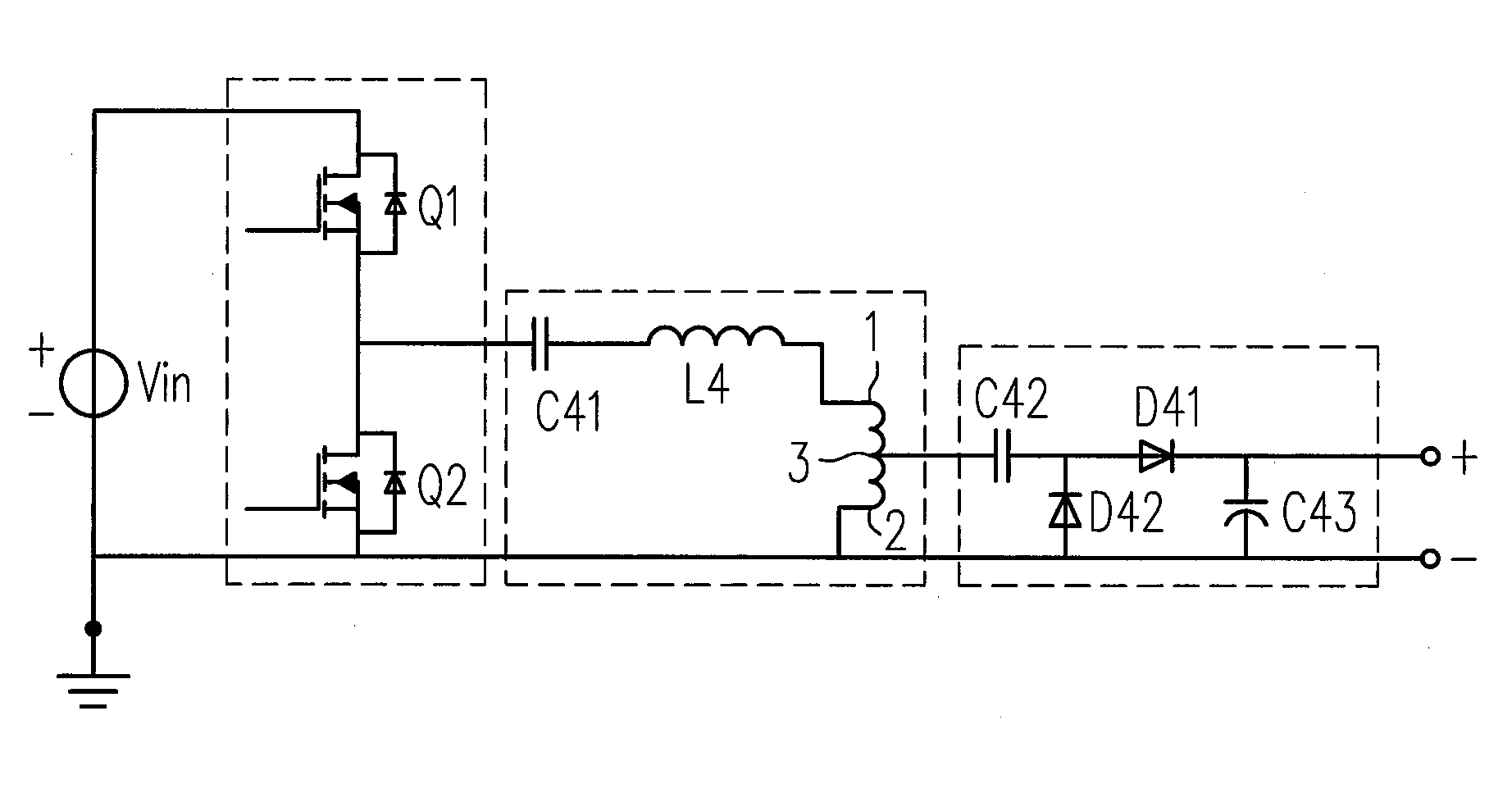
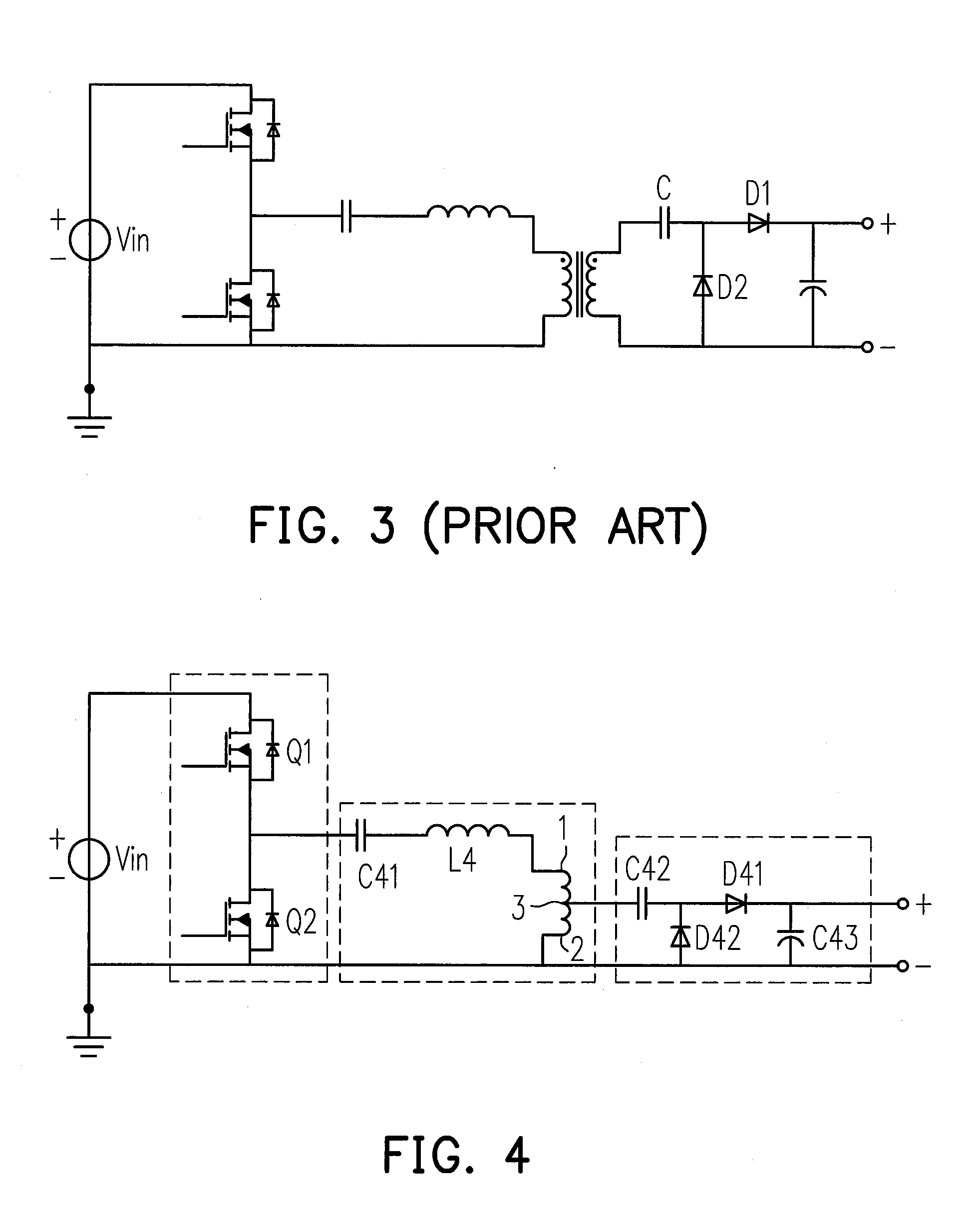
[0044]Referring to FIG. 21, the present invention provides a non-isolated resonant converter. The non-isolated resonant converter mainly includes three parts: a switch circuit, a resonant circuit and a rectifying-filtering circuit. The switch circuit, the resonant circuit and the rectifying-filtering circuit are sequentially connected. The resonant circuit includes an auto-transformer, a capacitor and an inductor, wherein the capacitor and the inductor are connected to the auto-transformer. It should be noted that the capacitor and the inductor ...


PUM


Abstract

A non-isolated resonant converter is provided. The provided non-isolated resonant converter includes a switch circuit, a resonant circuit and a rectifying-filtering circuit. The switch circuit, the resonant circuit and the rectifying-filtering circuit are sequentially connected. The resonant circuit includes an auto-transformer, a capacitor and an inductor, wherein the capacitor and the inductor are connected to the auto-transformer. The configuration of the provided non-isolated resonant converter has small size, low loss and high power density.

Description

CROSS-REFERENCE TO RELATED APPLICATION[0001]This application claims the priority benefit of China application serial no. 201110120398.9, filed on May 11, 2011. The entirety of the above-mentioned patent application is hereby incorporated by reference herein and made a part of this specification.BACKGROUND OF THE INVENTION[0002]1. Field of the Invention[0003]The present invention generally relates to a power conversion field, in particular, to a non-isolated resonant converter applied to photovoltaic inverters, LED constant-current driving and multi-path LED constant-current driving.[0004]2. Description of Related Art[0005]High frequency, high efficiency and high power density are the developing trends of switching power supply. By the characteristics of soft switching and great EMI performance, the resonant converter becomes important research issues in the power conversion technology field.[0006]Most of the common resonant converter is formed based on the isolated transformer. Refe...

Claims


Application Information

Patent Timeline
15 Nov 2012
Publication
US20120287678A1
IPC
H02M3/335
CPC
Y02B70/1433; Y02B70/1425; H02M2001/0058; H02M3/158; H02M3/33569; Y02B70/1491; Y02B70/10; H02M1/0058
Inventors
XU, MING; LI, XINLEI