Reciprocating pump with intersecting bore geometry

a reciprocating pump and bore technology, applied in the direction of machines/engines, liquid fuel engines, positive displacement liquid engines, etc., can solve the problems of high stress concentration, high stress concentration, and fatigue failure of the pump housing near the fluid chamber, so as to reduce the tensile stress

Inactive Publication Date: 2012-11-15
S P M FLOW CONTROL
View PDF3 Cites 46 Cited by
  • Summary
  • Abstract
  • Description
  • Claims
  • Application Information

AI Technical Summary

Benefits of technology

[0005]In a first aspect, there is provided a reciprocating pump housing including a suction valve bore and a discharge valve bore disposed along a first centerline and a plunger bore and an access bore disposed along a second centerline. The second centerline is substantially perpendicular to the first centerline. The pump housing also includes a first annular transition zone extending between an intersection of the plunger bore and suction valve bore and an intersection of the access bore and discharge valve bore. The first annular transition zone includes a curvature along its length to blend the intersections between the suction valve bore, the discharge valve bore, the plunger bore and the access bore. The pump

Problems solved by technology

One common problem associated with operating reciprocating pumps at alternating high and low pressures is fatigue failure in the pump housing near the fluid chamber.
Unfortunately, stress concentrations arise at these intersections during high pressure pu

Method used


Image

  • Reciprocating pump with intersecting bore geometry
  • Reciprocating pump with intersecting bore geometry
  • Reciprocating pump with intersecting bore geometry

Examples


Embodiment Construction

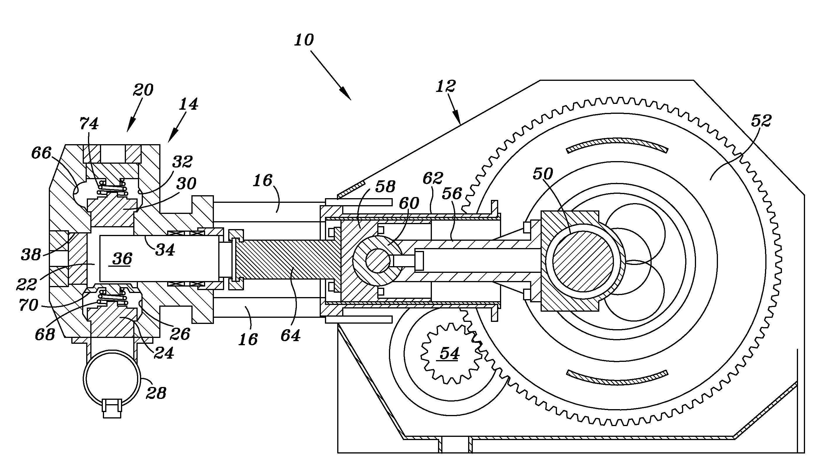
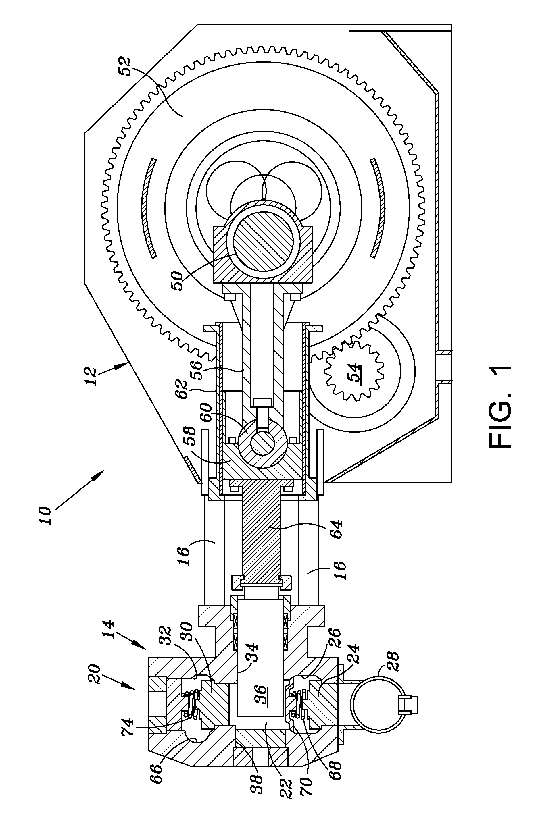
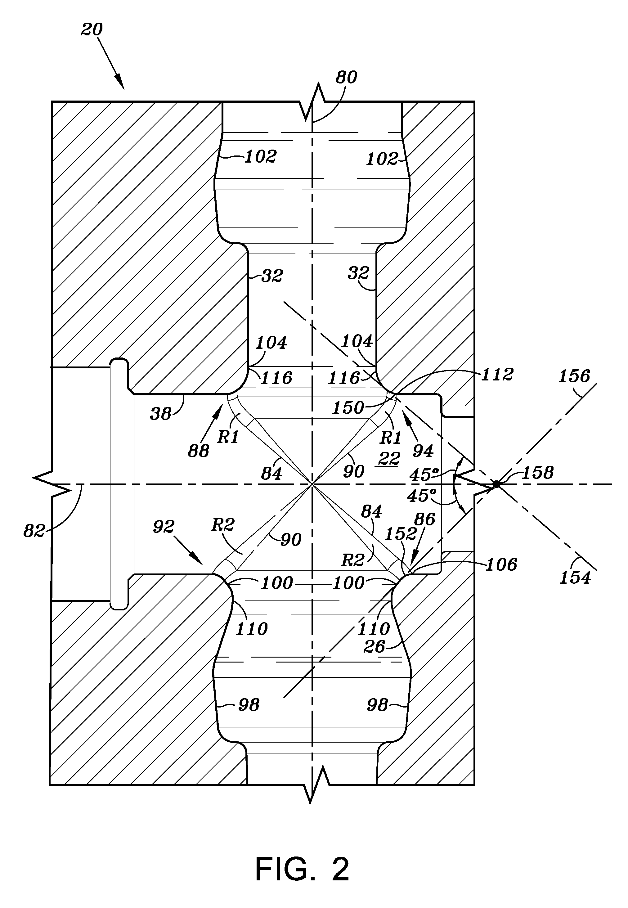
[0062]FIG. 1 is an illustration of a reciprocating pump assembly 10 having a crankshaft housing 12 operatively coupled to a fluid section 14 via the stay rods 16, the assembly 10 effective to pump fluid through a pump housing 20. The pump housing 20 includes one or more fluid chambers 22 (only one shown), which as explained in further detail below, are geometrically configured to minimize and and / or substantially eliminate fatigue failure that occurs in the general vicinity of the fluid chamber 22. In particular, the pump housing 20 typically includes a suction valve 24 in a suction bore 26 that draws fluid from within a suction manifold 28, a discharge valve 30 in a discharge bore 32 to control fluid output, a plunger bore 34 for housing a reciprocating plunger 36, and an access bore 38 to enable or otherwise facilitate access to the plunger bore 34. Such pump housings 20 are designed so that the suction valve bore 26, the discharge valve bore 32, the plunger bore 34 and the access...


PUM

PropertyMeasurementUnit
Fractionaaaaaaaaaa
Fractionaaaaaaaaaa
Fractionaaaaaaaaaa

Abstract

A reciprocating pump housing having a suction valve bore, a discharge valve bore, a plunger bore and an access bore. The suction and discharge bores are disposed on a first centerline and the plunger and access bores are disposed along a second centerline perpendicular to the first centerline. The pump housing includes a first annular transition zone extending between an intersection of the plunger bore and suction bore and an intersection of the access bore and the discharge valve bore. The housing also includes a second annular transition zone extending between an intersection of the suction valve bore and access bore and an intersection of the plunger bore and discharge valve bore. The first and second transition zones intersect along a third centerline perpendicular to the intersection of first and second centerlines, each including a curvature along their lengths to blend the intersections between the bores and reduce tensile stresses.

Description

CROSS-REFERENCE TO RELATED APPLICATIONS[0001]This application claims priority to U.S. Provisional Patent Application Ser. No. 61 / 477,471, filed on Apr. 20, 2011, which is incorporated herein by reference in its entirety.TECHNICAL FIELD[0002]This disclosure relates in general to reciprocating pumps, more particularly to the pump fluid housing thereof, and even more particularly to the design of the pump fluid housing to reduce fatigue failure thereof.BACKGROUND OF THE DISCLOSURE[0003]Large pumps are commonly used for mining and oilfield applications, such as, for example, hydraulic fracturing. During hydraulic fracturing, fracturing fluid (i.e., cement, mud, frac sand and other material) is pumped at high pressures into a wellbore to cause the producing formation to fracture. One commonly used pump in hydraulic fracturing is a high pressure reciprocating pump, like the SPM® Destiny™ TWS 2500 frac pump, manufactured by S.P.M. Flow Control, Inc. of Fort Worth, Tex. In operation, the fr...

Claims


Application Information

Patent Timeline
IPC IPC(8): F04B53/00B23P15/00
CPCF04B53/10Y10T29/49236F04B53/16
Inventor FREED, WESLEY D.DILLE, MARK C.SKURDALSVOLD, SCOTT
Owner S P M FLOW CONTROL
Why Eureka
Try Eureka