Abutment for a dental implant

a technology for dental implants and abutments, applied in the field of abutments, can solve the problems of increased bruxism, insufficient absorbing of masticatory stress on the structure of artificial teeth, and material disadvantages of being too stiff and brittle, so as to reduce the danger of structural weakening of the abutment, improve mechanical retention, and improve the effect of retention

Inactive Publication Date: 2012-11-15
NORDIN PETER +1
View PDF23 Cites 9 Cited by
  • Summary
  • Abstract
  • Description
  • Claims
  • Application Information

AI Technical Summary

Benefits of technology

[0021]According to a second preferred configuration, the mechanical retentions can be provided by means of at least one retention groove that is provided at the circumferential surface of the body portion. Preferably, at least two longitudinal grooves are provided extending in the apical direction of the body portion, wherein the course of each groove extends over a different portion of the circumference of the body portion. In this way, an improved retention can be achieved, wherein the danger of a structural weakening of the abutment is minimised. More preferred, the groove extends over the whole length of the body portion in order to increase mechanical retention along its total length. Moreover, the groove preferably exhibits an inclined course with respect to the longitudinal axis of the body portion for allowing an improved retention, in particular a substantially helical form that is at least partially winding or wrapped around the body portion. The preferred width and/or depth of the grooves is at least 0.01 mm and at most 1 mm, wherein a range in between 0.1 mm and 0.5 mm is more preferred. Preferably, at most ten, more preferred at most five, retention grooves are provided in order to minimize a structural weaking of the body portion. Other preferred characteristics of such a retention groove are described in patent application No. EP 2 281 525 A2, which is herewith enclosed by reference.
[0022]According to a third preferred configuration, an improved retention of the dental prosthesis on the abutment is achieved by combining both types of retention structures.
[0023]Preferably, the contact surface is constituted by a substantially flat bottom surface at the apical end of the body portion. This allows an easy application and positioning of the abutment on the dental implant before its actual fixation. Various fixation methods of the abutment on the implant are conceivable, in particular cementing, screwing or clipping or a combination thereof. Fixation by screwing can be achieved by means of an inward thread or an outward thread in or on the abutment. A particularly advantageous fixation of the abutment on the implant can be achieved in that a receiving bore is provided at the contact surface for receiv...

Problems solved by technology

All these materials have the disadvantage of being too stiff and brittle as compared to the natural dentine they are supposed to replace and mimic.
In consequence, the masticatory stresses exerted on the artificial tooth structure cannot be adequately absorbed.
This leads to a number of undesirable side effects including an unnatural feeling of pressure while chewing, increased bruxism, and an increased risk of breakage of the artificial tooth structure.
Anot...

Method used


Image

  • Abutment for a dental implant
  • Abutment for a dental implant
  • Abutment for a dental implant

Examples


Embodiment Construction

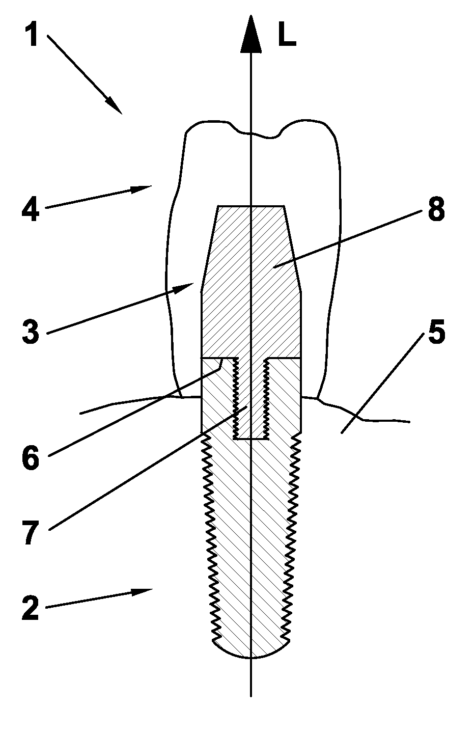
[0029]FIG. 1 depicts an artificial tooth structure 1 comprising a dental implant 2, an abutment 3 and a dental prosthesis 4. The dental implant 2 is anchored into a jaw bone 5 and consists, for instance, of titanium, stainless steel, ceramics or another osseointegratable material.

[0030]The abutment 3 is arranged on the dental implant 2 in such a way that the abutment 3 has a contact surface 6 at its apical end with the coronal side of the implant 2. The abutment 3 is rigidly connected to the implant 2 by means of a connector portion 7 protruding from the center of the contact surface 6. The connector portion 7 is cylindrically shaped and has an outer thread that is engaged with an inner thread of a receiving bore in the implant 2.

[0031]The abutment 3 further comprises a body portion 8 which constitutes a prolongation of the implant 2 in a coronal direction along the longitudinal axis L. At the surface of the body portion 8 the dental prosthesis 4 is attached.

[0032]The abutment 3 is ...


PUM


Abstract

The invention relates to an abutment for connecting a dental prosthesis to a dental implant, the abutment comprising a body portion for supporting the dental prosthesis and a contact surface apical to said body portion for contacting the dental implant.
In order to allow an adjustment of the tooth restoration structure to properties of a natural tooth the abutment is composed of a resin that is reinforced with fibers substantially extending over the total length of said body portion towards said contact surface.

Description

FIELD OF THE INVENTION[0001]The invention relates to an abutment for connecting a dental prosthesis to a dental implant, the abutment comprising a body portion for supporting the dental prosthesis and a contact surface apical to said body portion for contacting the dental implant.BACKGROUND OF THE INVENTION[0002]Prosthodontic restorations replacing a natural tooth in a patient's dentition are commonly fixed on a dental implant that is surgically implanted into the patient's jawbone. Typically, since the early work of Per-Ingvar Brånemark of Sweden in 1952, such an implant consists of a titanium screw which resembles a tooth root and comprises a roughened or smooth surface. The majority of dental implants are made out of pure titanium, which is commercially available in four grades depending upon the amount of contained carbon and iron.[0003]An abutment is usually anchored at the coronal end of the dental implant. A dental prosthesis, such as a crown, a fixed bridge retainer or a rem...

Claims


Application Information

Patent Timeline
IPC IPC(8): A61C8/00
CPCA61C8/0012A61C8/0074A61C8/0069A61C8/005
Inventor NORDIN, PETERNORDIN, HARALD
Owner NORDIN PETER
Why Eureka
Try Eureka