Floating wafer track with lateral stabilization mechanism

a technology of lateral stabilization and floating wafers, applied in the field of semiconductor processing, can solve the problems of destabilized substrates colliding with, stuck between said walls, and becoming destabilized, and achieve the effect of safe transportation environment and facilitation of a variety of semiconductor treatments

Inactive Publication Date: 2012-11-22
ASM INTERNATIONAL
View PDF11 Cites 24 Cited by
  • Summary
  • Abstract
  • Description
  • Claims
  • Application Information

AI Technical Summary

Benefits of technology

[0006]The apparatus according to the present invention may be employed to facilitate a variety of semiconductor treatments. In one embodiment, for example, the apparatus may be set up as a spatial atomic layer deposition apparatus featuring at least one depositing gas bearing, which bearing may comprise a number of spatially separated reactive materials or precursors. To this end, gas injection channels in at least one of the lower wall and the upper wall may, viewed in the transport direction, be successively connected to a first precursor gas source, a purge gas source, a second precursor gas source and a purge gas source, so as to create a process tunnel segment that—in use—comprises successive zones including a first

Problems solved by technology

A problem with substrates thus supported is that they may become destabilized by the gas flows necessary to maintain the gas bearings.
Along narrow tracks bounded by lateral walls, which themselves may be favorable for reasons of economic gas flow management, the lack of circular symmetry may cause destabilized substrates to collide with and get stuck between said walls.

Method used


Image

  • Floating wafer track with lateral stabilization mechanism
  • Floating wafer track with lateral stabilization mechanism
  • Floating wafer track with lateral stabilization mechanism

Examples


Embodiment Construction

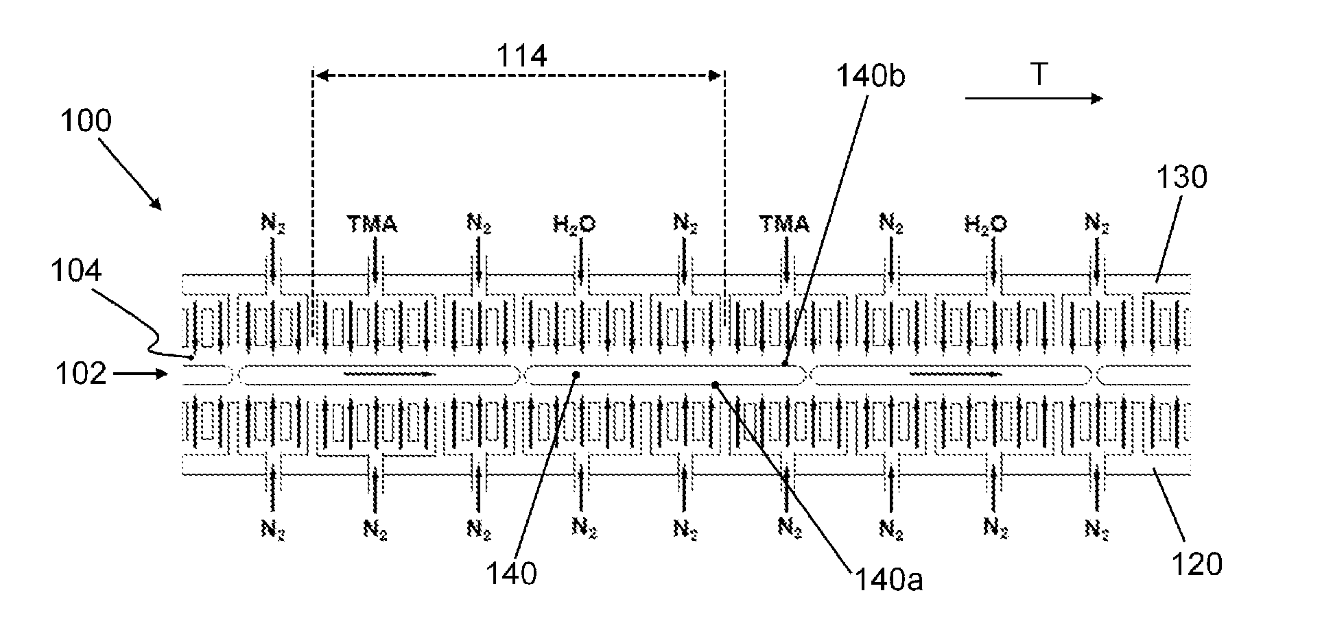
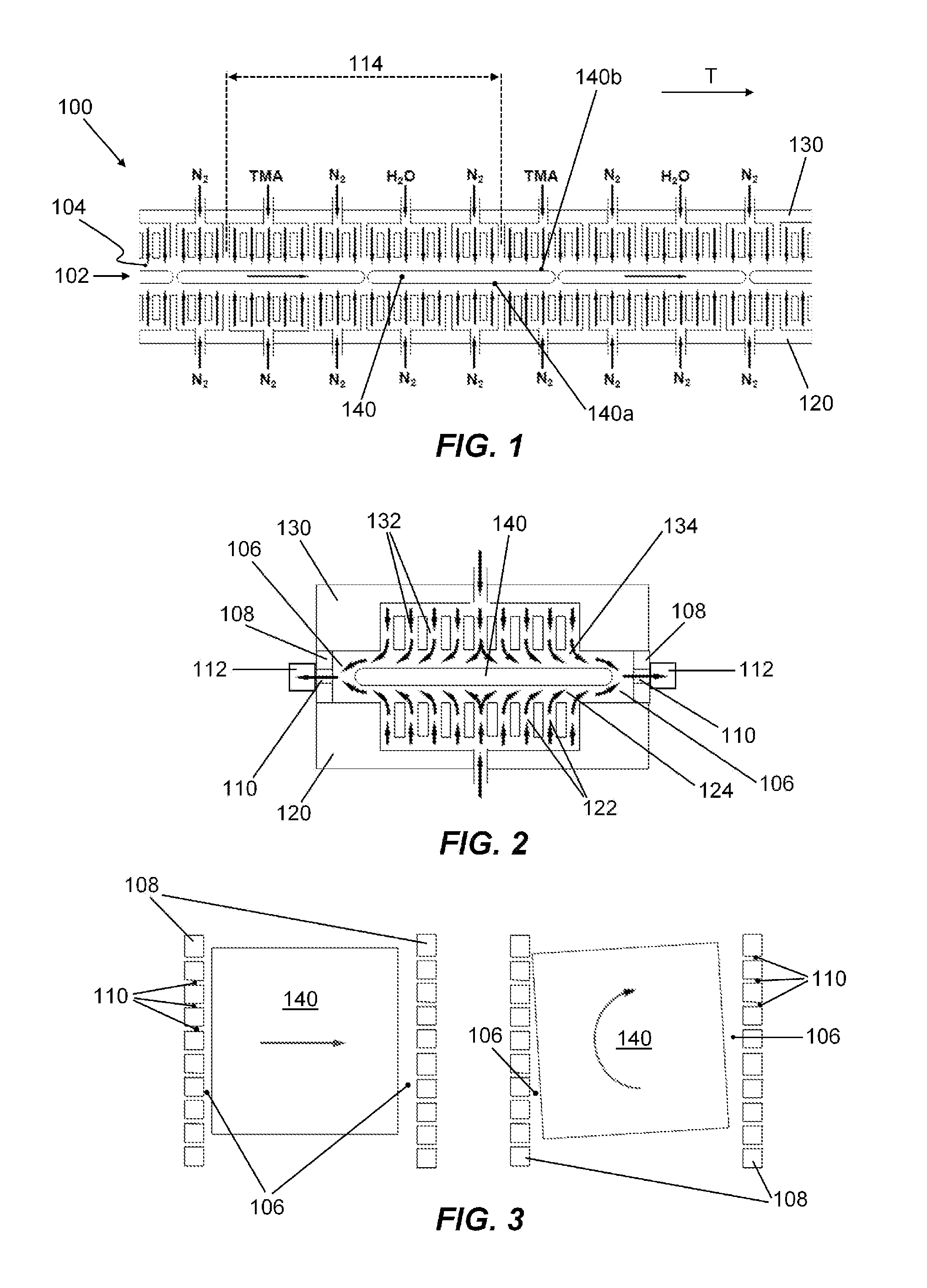
[0017]The construction of the apparatus according to the present invention will be described below in general terms. In doing so, reference will be made to the exemplary embodiment shown in FIGS. 1 and 2, which is set up as a spatial atomic layer deposition (ALD) apparatus. FIG. 1 is a diagrammatic longitudinal cross-sectional view of a portion of the exemplary ALD apparatus wherein the upper and lower walls of the process tunnel are configured asymmetrically. FIG. 2 is a diagrammatic lateral cross-sectional view of the exemplary atomic layer deposition apparatus shown in FIG. 1.

[0018]The disclosed apparatus 100 according to the present invention may include a process tunnel 102 through which a substrate 140, e.g. a silicon wafer, preferably as part of a train of substrates, may be conveyed in a linear manner. That is, the substrate 140 may be inserted into the process tunnel 102 at an entrance thereof to be uni-directionally conveyed to an exit. Alternatively, the process tunnel 10...


PUM

PropertyMeasurementUnit
Lengthaaaaaaaaaa
Fractionaaaaaaaaaa
Lengthaaaaaaaaaa

Abstract

An apparatus (100) comprising:—a process tunnel (102) including a lower tunnel wall (120), an upper tunnel wall (130), and two lateral tunnel walls (108), wherein said tunnel walls together bound a process tunnel space (104) that extends in a transport direction (T);—a plurality of gas injection channels (122, 132), provided in both the lower and the upper tunnel wall, wherein the gas injection channels in the lower tunnel wall are configured to provide a lower gas bearing (124), while the gas injection channels in the upper tunnel wall are configured to provide an upper gas bearing (134), said gas bearings being configured to floatingly support and accommodate said substrate there between; and—a plurality of gas exhaust channels (110), provided in both said lateral tunnel walls (108), wherein the gas exhaust channels in each lateral tunnel wall are spaced apart in the transport direction.

Description

FIELD OF THE INVENTION[0001]The present invention relates to the field of semiconductor processing, and more in particular to an apparatus configured to floatingly support and process a train of substantially rectangular wafers.BACKGROUND[0002]During semiconductor device fabrication semiconductor substrates or wafers may be subjected to a variety different treatments such as, for example, deposition and annealing. An apparatus for performing these treatments may be configured to process the substrates in continuous succession, which may offer improved throughput rates relative to alternative batch systems. Accordingly, said apparatus may feature a linear track or path along which the substrates may be transported while being processed.[0003]To simplify the design of such an apparatus, and to reduce the need for periodic maintenance, substrates may preferably be transported along the track by means of a ‘contactless’ method, i.e. a method that does not employ mechanical components th...

Claims


Application Information

Patent Timeline
IPC IPC(8): C23C16/455
CPCH01L21/67784C23C16/45551B65G49/065H01L21/6838B65G2249/045C23C16/4412C23C16/45548C23C16/4582H01L21/02178H01L21/0228
Inventor GRANNEMAN, ERNST HENDRIK AUGUST
Owner ASM INTERNATIONAL
Why Eureka
Try Eureka