Method and control unit for operating a valve

a valve and control unit technology, applied in the direction of electric control, magnetic bodies, machines/engines, etc., can solve the problems of insufficient evaluation accuracy of conventional methods, and it is more difficult to detect a predefinable characteristic in the auxiliary variable using conventional methods, so as to achieve precise evaluation

a valve and control unit technology, applied in the direction of electric control, magnetic bodies, machines/engines, etc., can solve the problems of insufficient evaluation accuracy of conventional methods, and it is more difficult to detect a predefinable characteristic in the auxiliary variable using conventional methods, so as to achieve precise evaluation

US20120291757A1Inactive Publication Date: 2012-11-22ROBERT BOSCH GMBH

Image

  • Method and control unit for operating a valve
  • Method and control unit for operating a valve
  • Method and control unit for operating a valve

Examples


Embodiment Construction

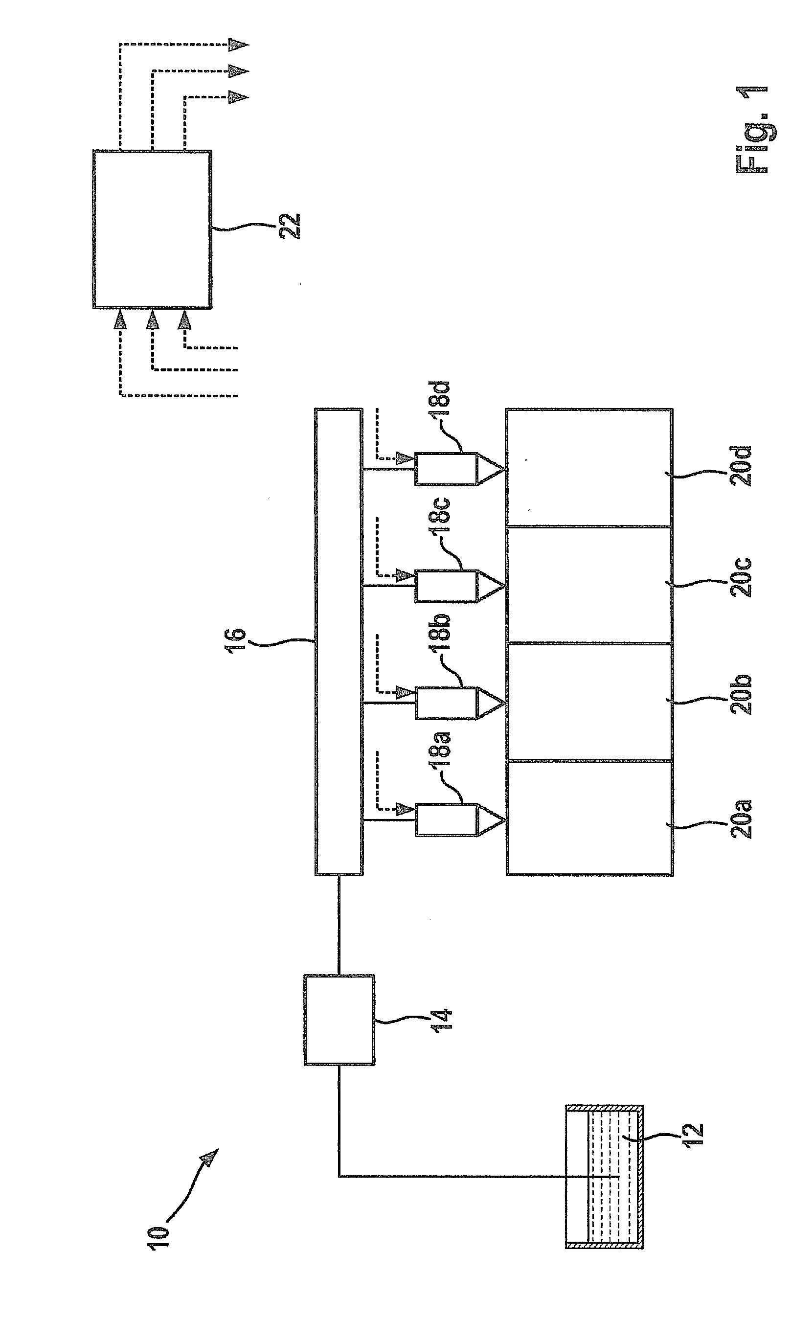
[0026]In FIG. 1, an internal combustion engine is identified as a whole by reference numeral 10. It includes a tank 12 from which a delivery system 14 delivers fuel to a common rail 16. Multiple electromagnetically actuated injectors 18a through 18d, which inject the fuel directly into combustion chambers 20a through 20d assigned to them, are connected thereto. The operation of internal combustion engine 10 is controlled or regulated by a control and regulating system 22, which activates injectors 18a through 18d, among other things.

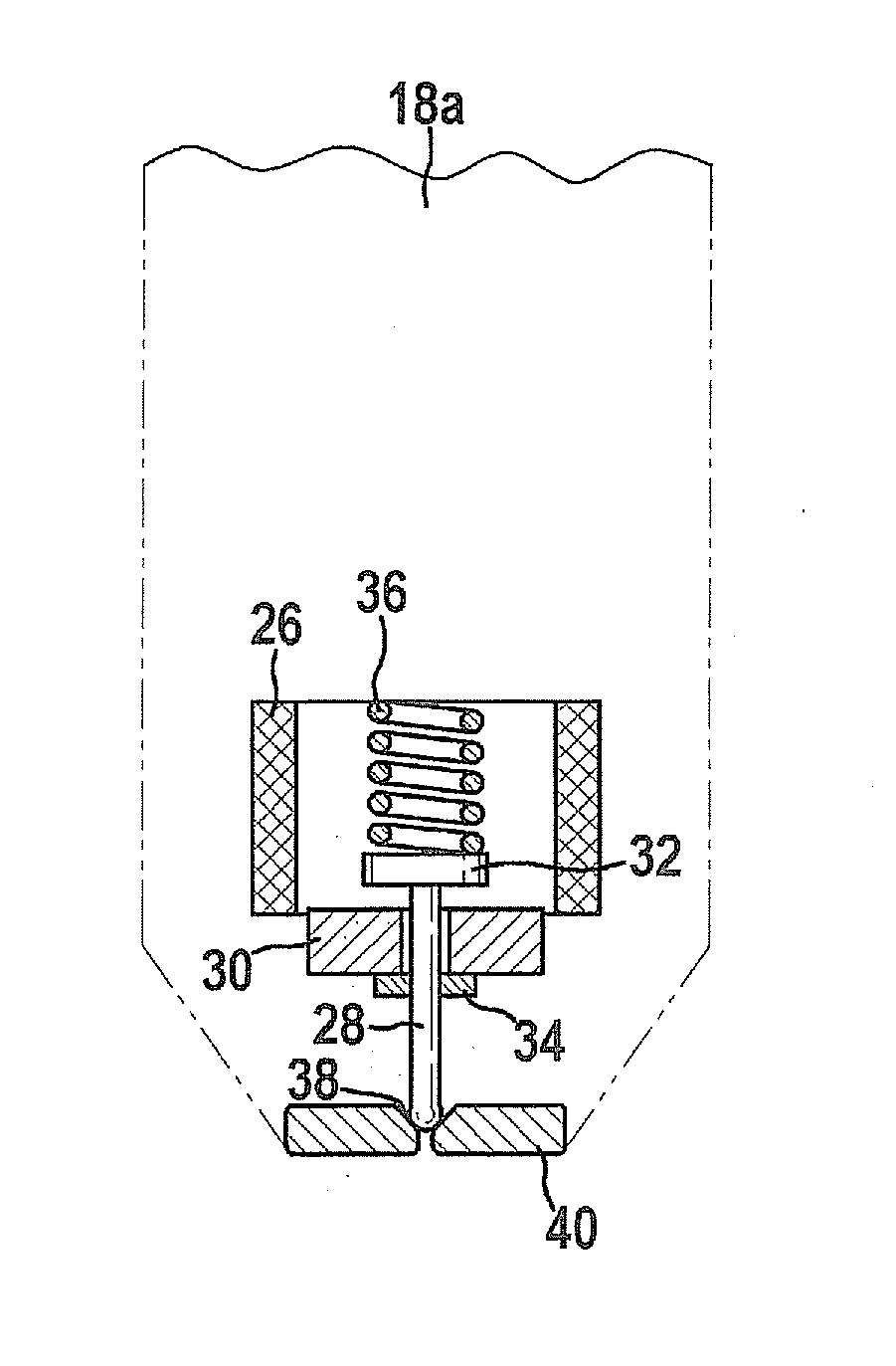
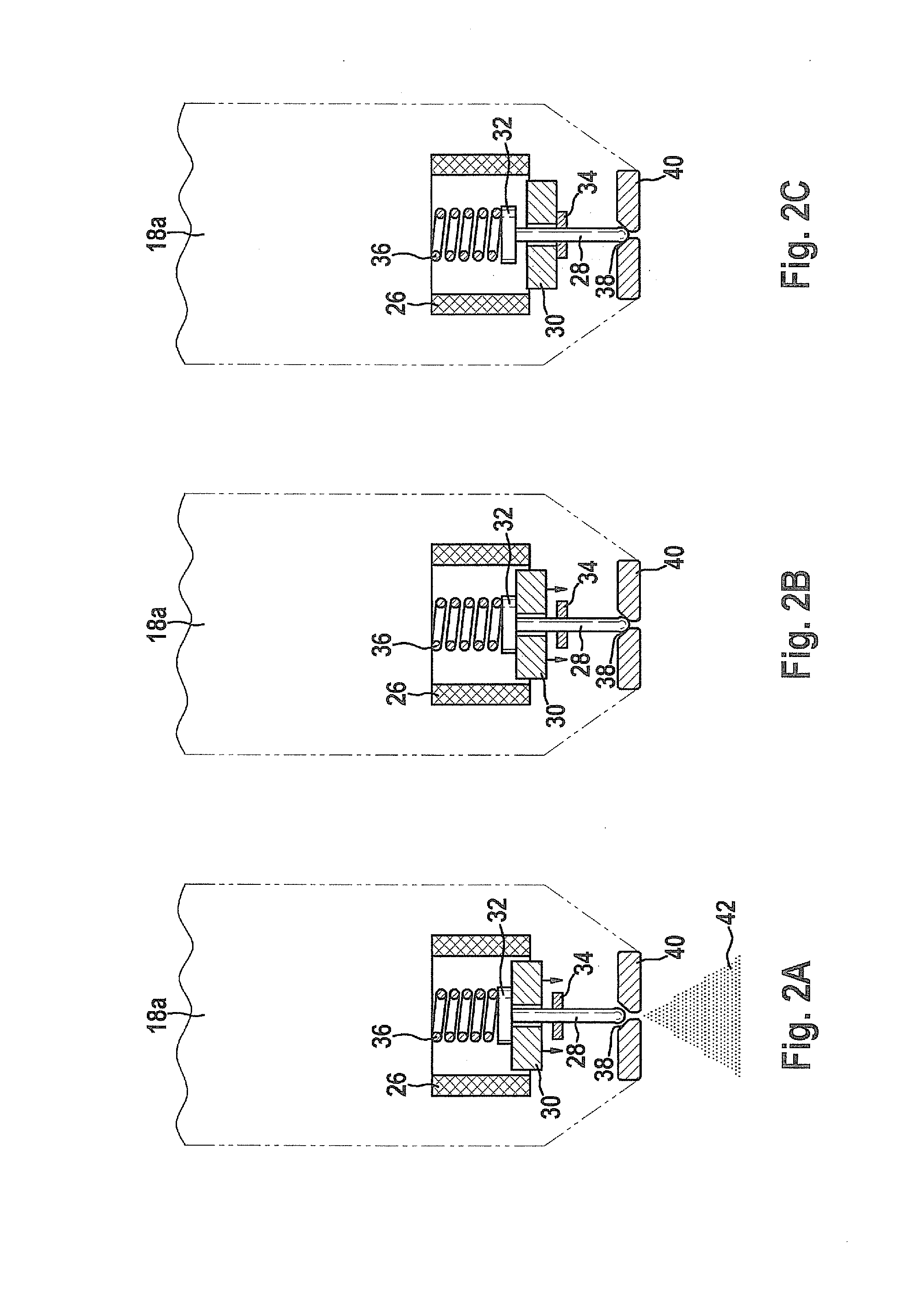
[0027]FIGS. 2a through 2c show schematic representations of injector 18a according to FIG. 1 in a total of three different operating states. The other injectors 18b, 18c, 18d, which are also illustrated in FIG. 1, have a corresponding structure and functionality.

[0028]Injector 18a has an electromagnetic actuator which includes a solenoid coil 26 and a solenoid armature 30 which cooperates with solenoid coil 26. Solenoid armature 30 is connected to a valv...


PUM


Abstract

A method for operating a valve, in particular a fuel injector of an internal combustion engine of a motor vehicle, in which an auxiliary variable is obtained as a function of at least one electrical operating variable of an electromagnetic actuator driving a component of the valve, in particular a valve needle, and in which the auxiliary variable is checked for the presence of a predefinable characteristic. A reference variable which characterizes the operating behavior of the electromagnetic actuator is ascertained, the auxiliary variable is modified as a function of the reference variable to obtain a modified auxiliary variable, and the modified auxiliary variable is checked for the presence of the predefinable characteristic.

Description

FIELD OF THE INVENTION[0001]The present invention relates to a method for operating a valve, in particular a fuel injector of an internal combustion engine of a motor vehicle, in which an auxiliary variable is obtained as a function of at least one electrical operating variable of an electromagnetic actuator driving a component of the valve, in particular a valve needle, and in which the auxiliary variable is checked for the presence of a predefinable characteristic. The present invention also relates to a control unit for operating a valve of this type.BACKGROUND INFORMATION[0002]Methods and devices of the aforementioned type are usually used to obtain information about an operating state of the valve. Particularly important changes in the operating state, for example a transition from an open state to a closed state, are derivable from extremes of a time characteristic of the auxiliary variable, at least in some operating modes or operating points of conventional injectors.[0003]H...

Claims


Application Information

Patent Timeline
22 Nov 2012
Publication
US20120291757A1
IPC
F02D41/20; F02D41/30; F02D41/26
CPC
F02D41/20; F02D41/2432; F02D41/247; H01F7/1844; F02D2041/2037; F02D2041/2055; F02D2041/1433
Inventors
JOOS, KLAUS; NEUBERG, JENS