Lighting driver circuit and light fixture

a driver circuit and light fixture technology, applied in the direction of electroluminescent light sources, electric lighting sources, semiconductor lamp usage, etc., can solve the problems of output voltage and luminance output rippling waveforms, and achieve the effect of suppressing blinking and flickering phenomena

Inactive Publication Date: 2012-11-22
PANASONIC CORP
View PDF5 Cites 26 Cited by
  • Summary
  • Abstract
  • Description
  • Claims
  • Application Information

AI Technical Summary

Benefits of technology

[0012]A lighting driver circuit and a light fixture according to aspects of the present invention can suppress blinking and flickering phenomena even when the light source is operated at a low luminance output.

Problems solved by technology

Output from a conventional lighting circuit as described above increases in the ON time during which the switching operation is performed and decreases in the OFF time during which the switching operation is stopped, thus causing a ripple waveform in the output voltage and luminance output.

Method used


Image

  • Lighting driver circuit and light fixture
  • Lighting driver circuit and light fixture
  • Lighting driver circuit and light fixture

Examples


Embodiment Construction

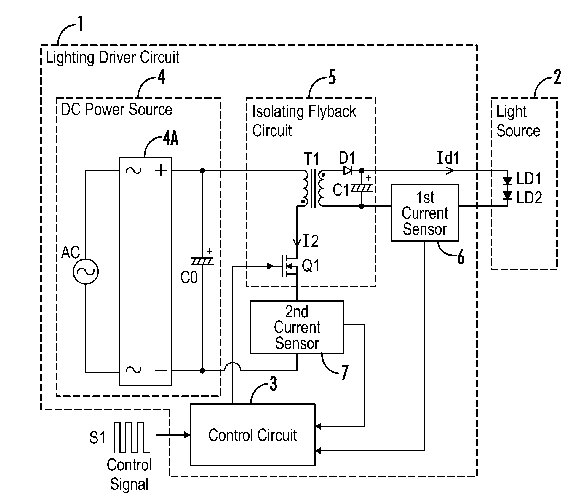
[0019]Referring to FIG. 1, a light fixture includes a light source 2 and a lighting driver circuit 1. The lighting driver circuit 1 controls a lighting state of the light source 2. The light source 2 includes one or a plurality of solid state light-emitting elements LD1, such as a light emitting diode (LED). In the present embodiment, two solid state light-emitting elements LD1 and LD2 are connected in series. The number of solid state light-emitting elements LD1 and method of connecting them together are not limited to those of the present embodiment, and they can be altered as appropriate to the embodiment. Moreover, the solid state light-emitting element LD1 is not limited to a light-emitting diode and may be another type of light-emitting element such as an organic EL.

[0020]The lighting driver circuit 1 includes: a DC power source 4, an isolating flyback circuit 5, and a control circuit 3. The isolating flyback circuit 5 switches the output from the DC power source 4 to light th...


PUM


Abstract

A lighting fixture that suppresses blinking and flickering phenomena even when operating at very low luminance levels includes: a light source including at least one solid state light-emitting element; and a lighting driver circuit controlling the light source in accordance with a control signal. The lighting driver circuit includes an isolating flyback circuit and a control circuit. The isolating flyback circuit switches power from a DC power source and smooths the output. The control circuit controls switching operation performed by a switching element of the isolating flyback circuit via PWM signal. The control circuit provides a frequency component in accordance with the control signal to a reference signal outputted by a reference signal generator. In accordance with results of detection of the reference signal and a current flowing through the light source, the control circuit provides a stop period during which a driver controller driving the switching element is stopped.

Description

[0001]A portion of the disclosure of this patent document contains material that is subject to copyright protection. The copyright owner has no objection to the reproduction of the patent document or the patent disclosure, as it appears in the U.S. Patent and Trademark Office patent file or records, but otherwise reserves all copyright rights whatsoever.CROSS-REFERENCES TO RELATED APPLICATIONS[0002]This application claims benefit of the following patent application which is hereby incorporated by reference: Japan Patent Application No. 2011-095034, filed Apr. 21, 2011.STATEMENT REGARDING FEDERALLY SPONSORED RESEARCH OR DEVELOPMENT[0003]Not ApplicableREFERENCE TO SEQUENCE LISTING OR COMPUTER PROGRAM LISTING APPENDIX[0004]Not ApplicableBACKGROUND OF THE INVENTION[0005]The present invention relates to a lighting driver circuit that lights a solid state light-emitting element such as a light emitting diode (LED), and a light fixtures that include LED driver circuits.[0006]Conventionally...

Claims


Application Information

Patent Timeline
Patent Type & Authority Applications(United States)
IPC IPC(8): H05B37/02H05B44/00
CPCY02B20/346H05B33/0815Y02B20/30H05B45/385
Inventor MATSUDA, KENJINAKAMURA, RYOSUKE
Owner PANASONIC CORP
Why Eureka
Try Eureka