Projector lens system and image display system using same

Inactive Publication Date: 2012-11-22
PANASONIC CORP
View PDF8 Cites 21 Cited by
  • Summary
  • Abstract
  • Description
  • Claims
  • Application Information

AI Technical Summary

Benefits of technology

[0010]In view of such problems of the prior art, a primary object of the present invention is to provide a projector lens system and an image display system that can achi

Problems solved by technology

However, the projector lens system disclosed in Patent Document 2 is unable to provide a high resolution, a high brightness and a long focal length that are required for the projector lens system to be used in a small projector owing to a limited number of lens elements.
A high resolution, a high brightness and a long focal length can be achieved by increasing the number of lens elements, but it increases the length of the optical system, and prevents the compact design of the projector.
On the other hand, as the projector lens system disclosed

Method used


Image

  • Projector lens system and image display system using same
  • Projector lens system and image display system using same
  • Projector lens system and image display system using same

Examples


first embodiment

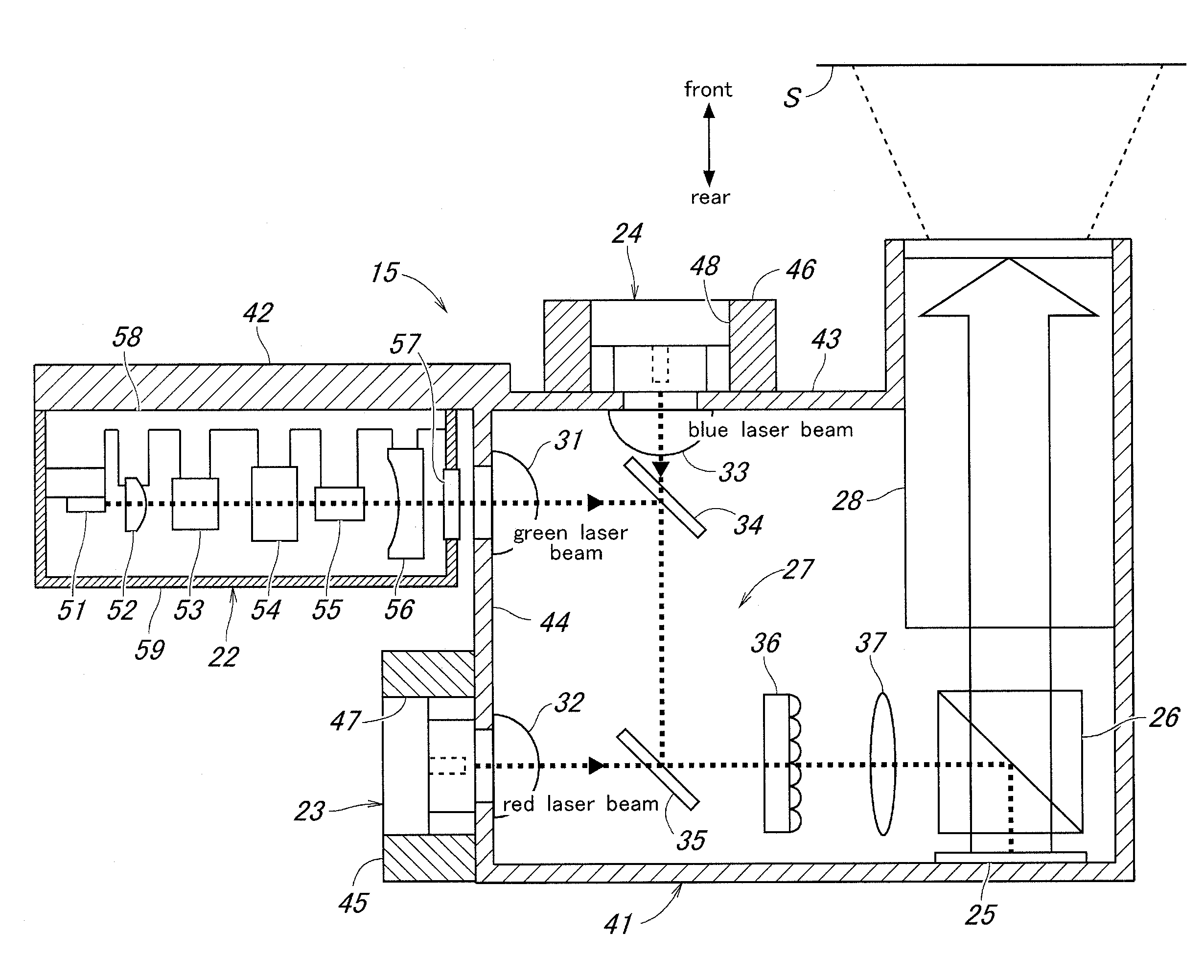
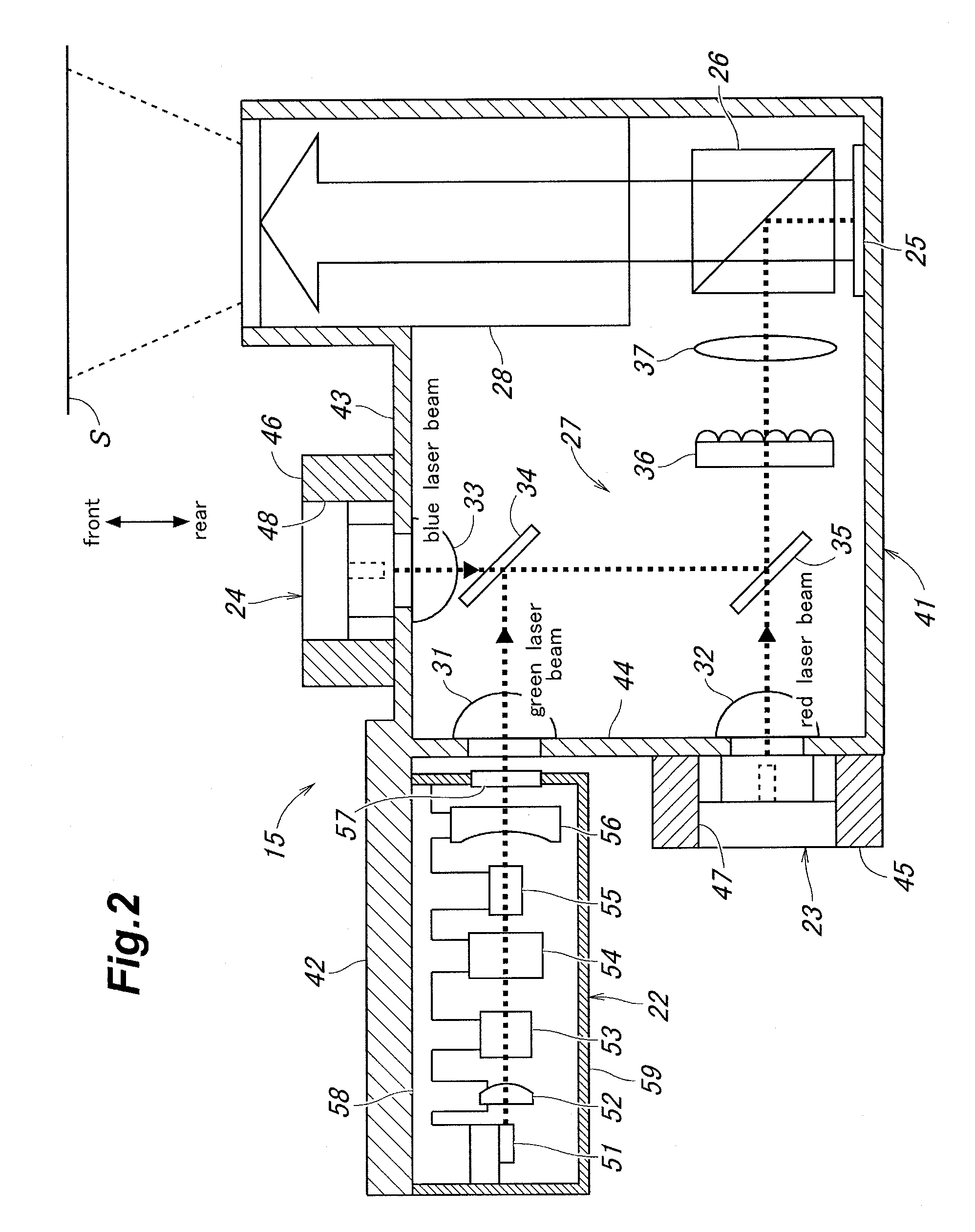
[0072]The specific arrangement of various lens elements in the projector lens system 28 according to the present invention is described in the following with reference to FIG. 4. The various components are shown in section, but are not hatched for the clarity of illustration. The modulated projected light emitted from the polarizing beam splitter 26 on the right hand side of FIG. 4 is projected onto the screen S shown on the left hand side of FIG. 4 via the projector lens system 28.

[0073]The projector lens system 28 includes a first lens element L1, a second lens element L2, a third lens element L3 and a fourth lens element L4, in that order from the first conjugate focal point on the projecting side (left side of FIG. 4), in a coaxial relationship. The first and fourth lens elements L1 and L4 are plastic lenses made of plastic material while the second and third lens elements L2 and L3 are glass lenses made of glass material. The projector lens system 28 is placed coaxially on the ...

second embodiment

[0178]As shown in FIGS. 21 to 25, the various optical aberrations are controlled within acceptable ranges. Similarly as in the second embodiment, the image height (P1) in FIG. 25a is 0 mm, the image height (P2) in FIG. 25b is 1.743 mm, the image height (P3) in FIG. 25c is 3.099 mm, and the image height (P4) in FIG. 25d is 3.556 mm.

[0179]The size of the optical modulator 25 in the first embodiment was 0.22inches, but it was increased to 0.28 inches in the third embodiment. Also, the glass material for the polarizing beam splitter 26 was BSC7 (a crown glass designated by the Optical Glass Industry Association of Japan) in the first embodiment, and was changed to SF57HHT (made by Schott AG of Mainz, Germany) in the third embodiment.

[0180]Owing to these changes, the MTF (modulation transfer function) which was 831 p / mm (off the axis 40%, on the axis 50%) in the first embodiment is increased to 1,001 p / mm (off the axis 40%, on the axis 50%) in the third embodiment, and it means a signifi...


PUM


Abstract

In a projector lens system including at least three lens elements and telecentric on a side of an optical modulator, two of the lens elements located on outer most ends of the projector lens system facing conjugate points of the projector lens system consist of plastic lenses, and an aperture stop of the projector lens system is located between the two outer most lens elements while at least one of the lens elements other than the two outer most lens elements most adjacent to the aperture stop consists of a glass lens. Thereby, the cost and weight of the projector lens system can be reduced while achieving the required optical properties.

Description

TECHNICAL FIELD[0001]1. Field of the Invention[0002]The present invention relates to a projector lens system and an image display system suitable for use in small projectors.[0003]2. Description of the Related Art[0004]In recent years, there is a growing interest in the use of the semiconductor laser as the light source of image display systems. The semiconductor laser has various advantages over the mercury lamp which is commonly used as the light source for more conventional image display systems, such as a better color reproduction, the capability to turn on and off instantaneously, a longer service life, a higher efficiency (or a lower power consumption) and the amenability to compact design.[0005]Such advantages are particularly beneficial when the image display system using a semiconductor laser is used in a portable electronic device such as a mobile phone (Patent Document 1: JP2007-316393A). The image display system incorporated in a portable electronic terminal can project ...

Claims


Application Information

Patent Timeline
IPC IPC(8): G03B21/14G02B13/04G02B13/22
CPCG02B13/04G03B21/005G02B13/22
Inventor INOUE, MASAHIROKADOWAKI, SHINICHI
Owner PANASONIC CORP
Why Eureka
Try Eureka