Systems and methods for identifying gaze tracking scene reference locations

Active Publication Date: 2012-11-22
GOOGLE LLC
View PDF22 Cites 284 Cited by
  • Summary
  • Abstract
  • Description
  • Claims
  • Application Information

AI Technical Summary

Benefits of technology

[0021]In any of these examples, illumination, reference location tracking, eye tracking and gaze tracking may be operated substantially continuously or intermittently. For example, scene light sources may be deactivated when the scene camera is inoperative. This includes

Problems solved by technology

As the distance away from the eyes is increased, an eye tracking apparatus generally becomes less obtrusive; however, it becomes increasingly difficult to accurately measure the location of an eye because of the need for higher spatial resolution by cameras an

Method used


Image

  • Systems and methods for identifying gaze tracking scene reference locations
  • Systems and methods for identifying gaze tracking scene reference locations
  • Systems and methods for identifying gaze tracking scene reference locations

Examples


Embodiment Construction

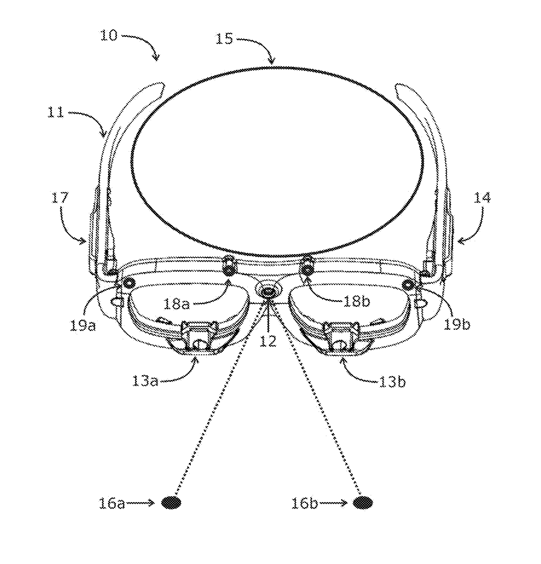
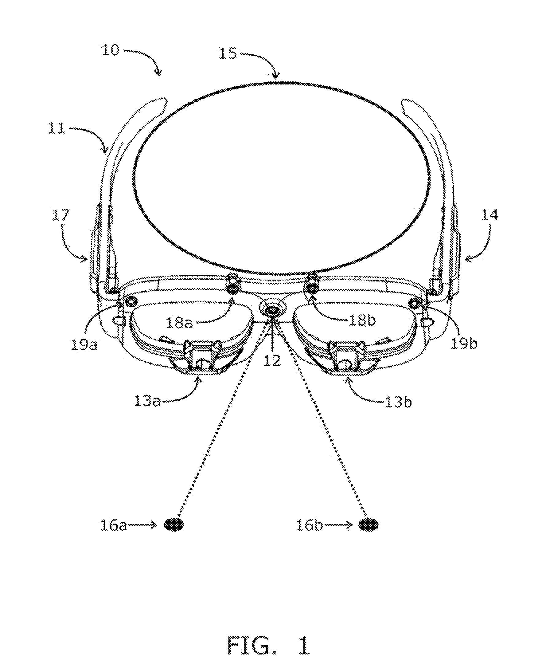
[0031]Turning to the drawings, FIG. 1 shows an exemplary embodiment of a system 10 including an eyeglass frame 11 with a scene camera 12, two eye-tracking cameras 13a, 13b, and a processing unit 14. Scene camera 12 is oriented on the frame 11 to view the region away from the device wearer's head 15 in order to track one or more reference locations 16a, 16b within the environment of the device wearer. Eye-tracking cameras 13a and 13b are oriented on the frame 11 toward the head 15 in order to track the locations of the wearer's pupils, glints, and / or other reference points on one or both eyes of the wearer.

[0032]In this embodiment, a single processing unit 14 may be carried by the frame 11, e.g., to acquire images from the scene camera 12 as well as the eye-tracking cameras 13a, 13b, although it will be appreciated that separate processors (not shown) may be provided on the frame 11 or at a remote location (not shown) that communicates with the frame 11. A power source (e.g., battery...


PUM


Abstract

A system is provided for identifying reference locations within the environment of a device wearer. The system includes a scene camera mounted on eyewear or headwear coupled to a processing unit. The system may recognize objects with known geometries that occur naturally within the wearer's environment or objects that have been intentionally placed at known locations within the wearer's environment. One or more light sources may be mounted on the headwear that illuminate reflective surfaces at selected times and wavelengths to help identify scene reference locations and glints projected from known locations onto the surface of the eye. The processing unit may control light sources to adjust illumination levels in order to help identify reference locations within the environment and corresponding glints on the surface of the eye. Objects may be identified substantially continuously within video images from scene cameras to provide a continuous data stream of reference locations.

Description

STATEMENT REGARDING FEDERALLY SPONSORED RESEARCH AND DEVELOPMENT[0001]The U.S. Government may have a paid-up license in this invention and the right in limited circumstances to require the patent owner to license others on reasonable terms as provided for by the terms of Department of Defense (US Army) Contract No. W81XWH-05-C-0045, U.S. Department of Defense Congressional Research Initiatives No. W81XWH-06-2-0037 and W81XWH-09-2-0141, and U.S. Department of Transportation Congressional Research Initiative Agreement Award No. DTNH 22-05-H-01424.FIELD OF THE INVENTION[0002]The present invention relates to apparatus, systems, and methods for unobtrusively identifying reference locations within the environment of a device wearer for gaze tracking and other applications.BACKGROUND OF THE INVENTION[0003]The apparatus, systems, and methods herein utilize machine vision techniques to track locations and objects being viewed by an observer. Gaze tracking algorithms can be considered as requ...

Claims


Application Information

Patent Timeline
IPC IPC(8): G06K9/00F21V21/084H04N7/18
CPCG06T2207/10016G06K9/00604G02B2027/0178G02B2027/0138G02B2027/014G02B2027/0187G06T2207/30204G02B27/017G02B27/0093G06F3/013G06T7/0044G06T2207/10024A61B3/113G06T7/74G06V40/19
Inventor PUBLICOVER, NELSON G.TORCH, WILLIAM C.AMAYEH, GHOLAMREZALEBLANC, DAVID
Owner GOOGLE LLC
Why Eureka
Try Eureka