Vehicle control system

a control system and vehicle technology, applied in the direction of electric control, machines/engines, instruments, etc., can solve the problems of driver's request or demand not being satisfied, and the driver may feel uncomfortable when such a change occurs, so as to increase the absolute value of the target output value

Inactive Publication Date: 2012-11-22
TOYOTA JIDOSHA KK
View PDF13 Cites 10 Cited by
  • Summary
  • Abstract
  • Description
  • Claims
  • Application Information

AI Technical Summary

Benefits of technology

[0007]The invention has been developed in view of the above-described situation, and provides a vehicle control system that is able to make the driver less likely or unlikely to feel uncomfortable during driving of the vehicle, while achieving a desired acceleration.
[0013]In the vehicle control system as described above, it is preferable that the increasing correction is to increase the absolute value of the target output value by multiplying the target output value by the gain.
[0014]In the vehicle control system as described above, it is preferable that the increasing correction is to increase the absolute value of the target output value by shifting the target output value by an offset value.
[0015]The vehicle control system according to the present invention increases the absolute value of the target output value by multiplying the target output value by the gain that depends on the operation of the accelerator member; therefore, when the driver requests a large acceleration, the requested acceleration can be achieved. Also, when the target output value becomes close to 0, the gain by which the target output value is multiplied is returned to a condition or value where the absolute value of the target output value is not increased; therefore, when the control of increasing the absolute value of the target output value with the gain is stopped, an elevation change or stepped change in the actual acceleration is less likely to occur or prevented from occurring. Consequently, the vehicle control system makes the driver less likely or unlikely to feel uncomfortable during driving of the vehicle, while achieving a desired acceleration.

Problems solved by technology

However, since the driver changes the manner of operating the accelerator pedal depending on a target acceleration, the driver's request or demand may not be satisfied if the target driving force is calculated only based on the accelerator pedal stroke.
However, if the target acceleration is corrected using information other than the accelerator pedal stroke, an elevation change or stepped change in the acceleration may occur when the control system returns from a condition where the correction is conducted, to a condition of normal acceleration control, and the driver may feel uncomfortable when such a change occurs in the acceleration.

Method used


Image

  • Vehicle control system
  • Vehicle control system
  • Vehicle control system

Examples


Embodiment Construction

[0029]A vehicle control system according to one embodiment of the invention will be described in detail with reference to the drawings. It is to be understood that this invention is not limited to the following embodiment. It is also to be understood that constituent elements of the invention include elements with which a person skilled in the art could easily replace constituent elements of the following embodiment, and elements that are substantially identical with the constituent elements of the embodiment.

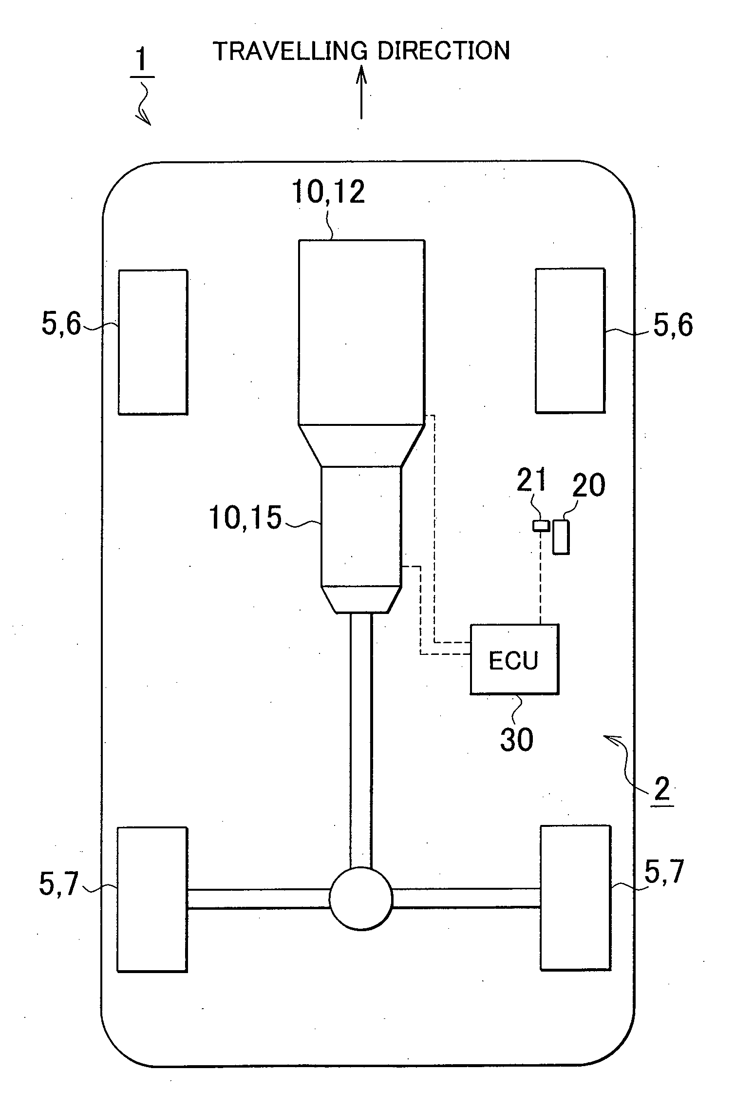
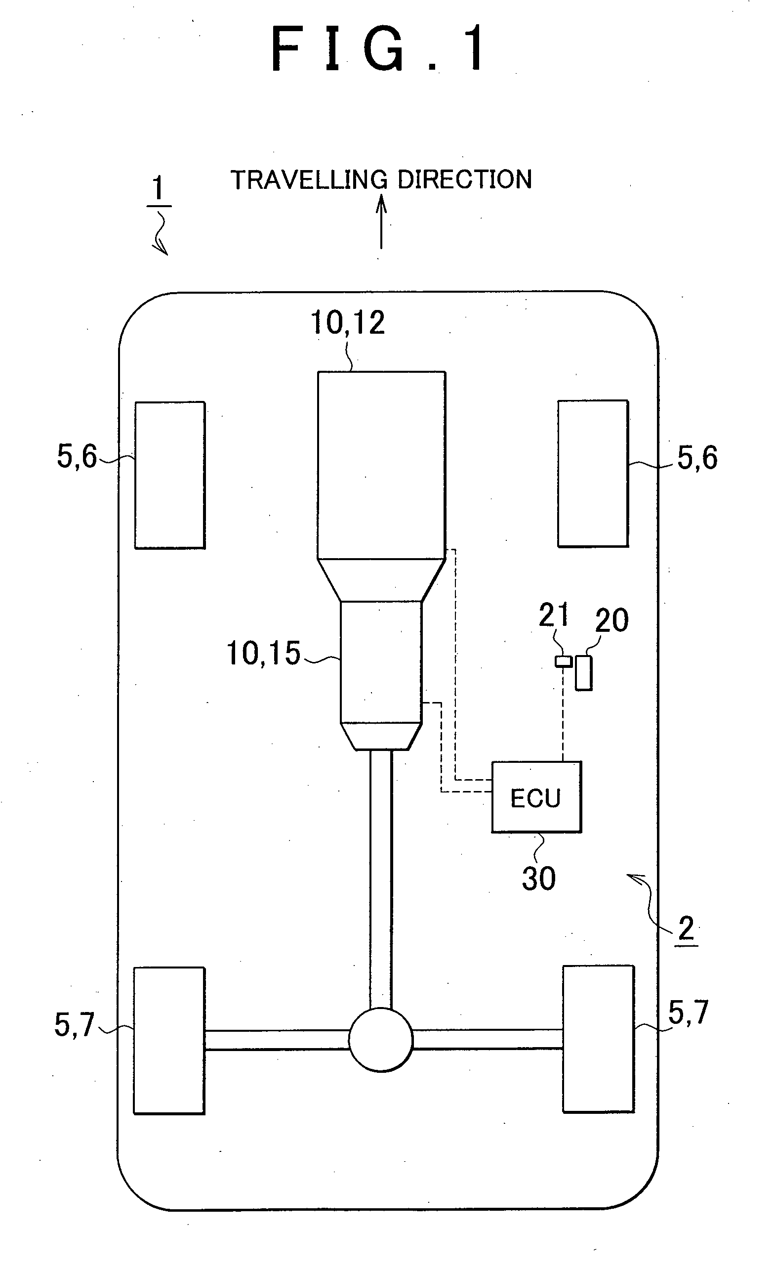
[0030]FIG. 1 is a schematic view of a vehicle in which the vehicle control system according to the embodiment of the invention is provided. An engine 12 as an internal combustion engine is installed as a power source on the vehicle 1 including the vehicle control system 2 of this embodiment, and the vehicle 1 is able to run with power of the engine 12. An automatic transmission 15 as one example of gear shifting device is connected to the engine 12, and the power generated by t...


PUM


Abstract

When the operating speed of an accelerator pedal is higher than a given operating speed, a target acceleration as a target output value is multiplied by a gain so that an absolute value of the target acceleration is increased; therefore, a large acceleration requested by the driver can be achieved. The gain by which the target acceleration is multiplied is set to 1 when the target acceleration is about zero, so as to resume a condition where the absolute value of the target acceleration is not increased. Thus, when the control of increasing the absolute value of the target acceleration with the gain is stopped, an elevation change is less likely or unlikely to occur in the actual acceleration. Consequently, a desired acceleration is generated without causing the driver to feel uncomfortable during driving of the vehicle.

Description

BACKGROUND OF THE INVENTION[0001]1. Field of the Invention[0002]The invention relates to a vehicle control system.[0003]2. Description of the Related Art[0004]The vehicle control system calculates target driving force based on the stroke (i.e., the amount of depression) of the accelerator pedal operated by the driver, and controls a drive system so that the drive system generates the target driving force requested by the driver. However, since the driver changes the manner of operating the accelerator pedal depending on a target acceleration, the driver's request or demand may not be satisfied if the target driving force is calculated only based on the accelerator pedal stroke. Therefore, some known types of vehicle control systems perform driving control, using operation information other than the accelerator pedal stroke.[0005]For example, in a vehicle motion control system as described in Japanese Patent Application Publication No. 2007-247579 (JP-A-2007-247579), the relationship...

Claims


Application Information

Patent Timeline
Patent Type & Authority Applications(United States)
IPC IPC(8): G06F17/00B60W30/00B60W30/18B60W50/06
CPCB60W10/06B60W10/10B60W50/06F02D2200/602F02D41/045F02D41/107F02D11/105B60W2540/10B60W2540/106B60W2720/106
Inventor MATSUSHITA, KOKINOUMURA, SHINKOIBUCHI, KEN
Owner TOYOTA JIDOSHA KK
Why Eureka
Try Eureka