Dewatering machine for umbrella

a dewatering machine and umbrella technology, applied in the direction of drying solid materials without heat, drying goods, lighting and heating equipment, etc., can solve the problems of people being prone to fall, ground slippery and slippery, environmental problems, etc., and achieve the effect of rapid and efficient dewatering process

Inactive Publication Date: 2012-11-29
LIAO ZHIFENG
View PDF15 Cites 4 Cited by
  • Summary
  • Abstract
  • Description
  • Claims
  • Application Information

AI Technical Summary

Benefits of technology

[0020]Advantages of the present invention are summarized below: the water throwing box is disposed inside the dewatering machine for umbrella and connected with the motor via the transmission assembly. The water throwing box is perpendicular to the transmission shaft to enable the umbrella to rotate above the plane direction where the umbrella is perpendicular to the transmission shaft; therefore rainwater on the umbrella, especially the folding umbrella, can be thrown out of the folds under the centrifugal force. The dewatering process is rapid and efficient.

Problems solved by technology

In rainy days, in office buildings, marketplaces, etc. with huge population, if rainwater on umbrellas drops to the ground, the ground will become slippery and people are likely to fall over.
It would also cause environmental problem.
In addition, it is inconvenient for people to carry wet umbrellas for shopping.
But if the bag is damaged, the rainwater will still drop to the ground to make it slippery.
As the folding umbrellas have many folds, it is difficult to completely remove the rainwater from the folds, the dewatering effect is poor.
It occupies a large area and it is inconvenient to be used.
It is inconvenient to be used and cannot be used indoors.
But in actual applications, the dewatering machines are mainly placed outdoors and it is inconvenient to use an external AC power supply.

Method used


Image

  • Dewatering machine for umbrella
  • Dewatering machine for umbrella
  • Dewatering machine for umbrella

Examples


Embodiment Construction

[0025]The present invention is described in further detail below with reference to the accompany drawings.

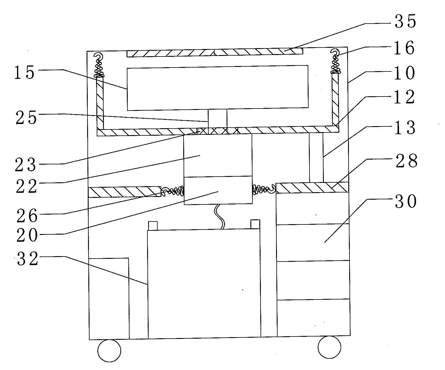
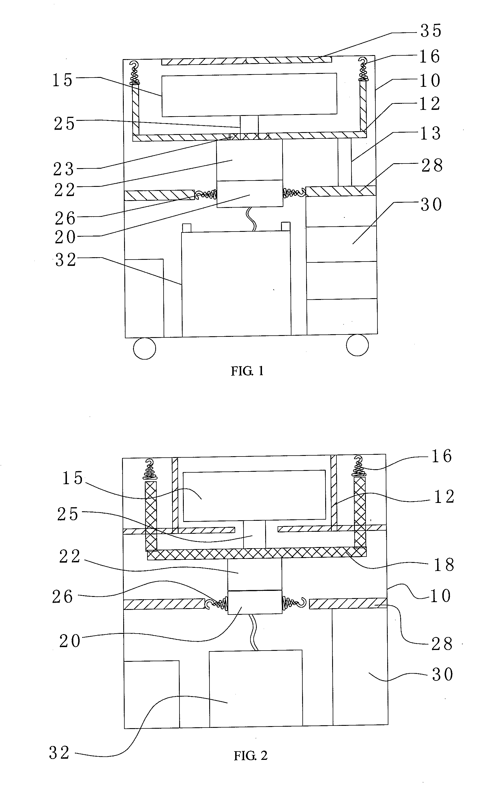
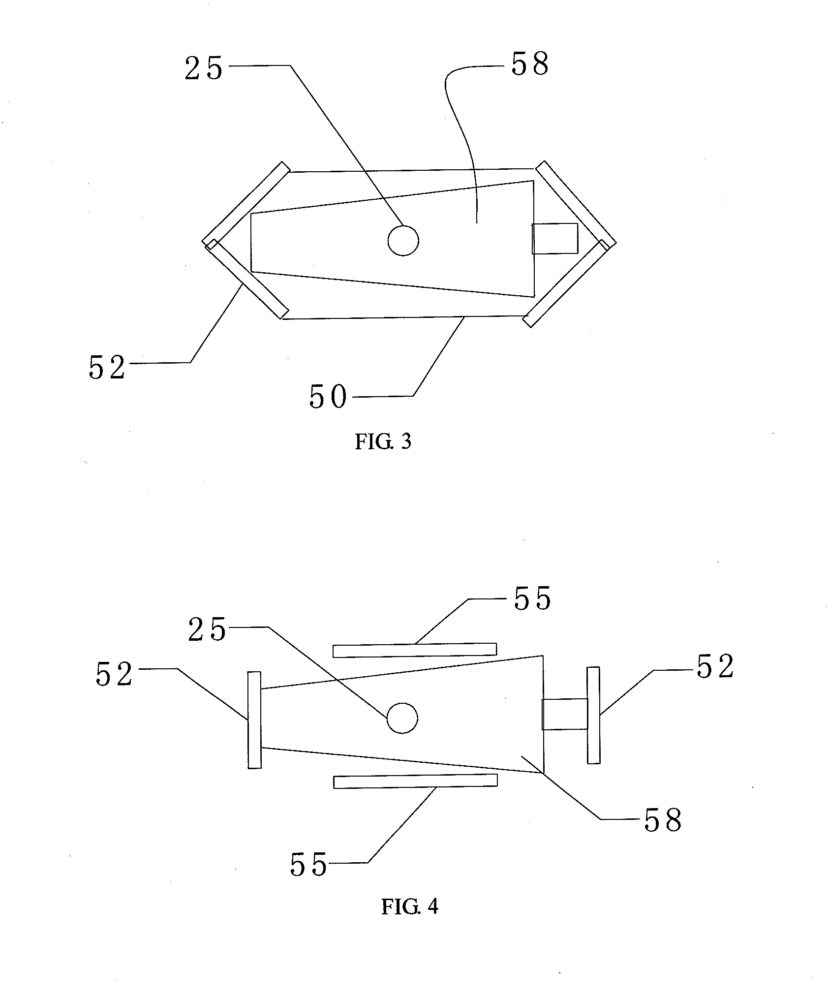
[0026]As shown in FIG. 1, a dewatering machine for umbrella, in accordance with the present invention, comprises a frame 10, a motor 20 disposed inside the frame 10, a water receiving box 12 disposed inside the frame 10, an elongated water throwing box 15 disposed inside the water receiving box 12 to accommodate the umbrella and a transmission assembly for connecting the motor 20 and the water throwing box 15. The water receiving box 12 is fixedly attached to the motor 20. A plurality of water-draining holes is disposed at the side and two ends of the water throwing box 15. The transmission assembly includes a transmission shaft 25 fixedly attached to the bottom center of the water throwing box 15. The transmission shaft 25 is perpendicular to the water throwing box 15. The frame 10 may be a machine case to accommodate various members of the machine. The transmission shaft 25 is...


PUM


Abstract

The present invention relates to a dewatering machine for umbrella, comprising a frame, a motor disposed inside the frame, a water receiving box disposed inside the frame, an elongated water throwing box disposed inside the water receiving box to accommodate the umbrella and a transmission assembly for connecting the motor and the water throwing box. The water receiving box is fixedly attached to the motor. A plurality of water-draining holes is disposed at the side of the water throwing box. The transmission assembly includes a transmission shaft fixedly attached to the bottom center of the water throwing box. The transmission shaft is perpendicular to the water throwing box. The water throwing box is disposed inside the dewatering device and connected with the motor via the transmission assembly. The water throwing box is perpendicular to the transmission shaft to enable the umbrella to rotate above the plane direction where the umbrella is perpendicular to the transmission shaft; therefore rainwater on the umbrella, especially the folding umbrella, can be thrown out of the folds under the centrifugal force. The dewatering process is rapid and efficient.

Description

FIELD OF THE INVENTION[0001]The present invention relates to a dewatering machine for umbrella.BACKGROUND OF THE INVENTION[0002]In rainy days, in office buildings, marketplaces, etc. with huge population, if rainwater on umbrellas drops to the ground, the ground will become slippery and people are likely to fall over. It would also cause environmental problem. In addition, it is inconvenient for people to carry wet umbrellas for shopping. In order to solve the above problem, a common solution is to put the umbrella in a bag. But if the bag is damaged, the rainwater will still drop to the ground to make it slippery.[0003]The dewatering machine for umbrella in the prior art comprises a drying drum, into which the umbrella is placed vertically. The drying drum rotates to create the centrifugal force to dry the umbrella. As the folding umbrellas have many folds, it is difficult to completely remove the rainwater from the folds, the dewatering effect is poor. The drying drum is in the sh...

Claims


Application Information

Patent Timeline
Patent Type & Authority Applications(United States)
IPC IPC(8): F26B5/08A45B25/28
CPCF26B2210/10F26B5/08
Inventor LIAO, ZHIFENG
Owner LIAO ZHIFENG
Why Eureka
Try Eureka