Moment calibrating apparatus for multi-component force gauge and method of moment calibration

a multi-component force gauge and moment calibration technology, applied in the direction of instruments, structural/machine measurement, weighing auxiliaries, etc., can solve the problems of affecting the workability of moment calibration, and reducing the accuracy of moment calibration, so as to achieve accurate and effective moment calibration

Inactive Publication Date: 2012-11-29
KOBE STEEL LTD
View PDF5 Cites 12 Cited by
  • Summary
  • Abstract
  • Description
  • Claims
  • Application Information

AI Technical Summary

Benefits of technology

[0011]The present invention, which was made in view of the aforesaid problems, therefore aims to provide a moment calibrating apparatus for a multi-component force gauge and a calibration method capable of calibrating a moment accurately and effectively.

Problems solved by technology

The calibration method is intended to separately calibrate the multi-component force gauge as a single unit removed from a tire testing apparatus, and not designed for calibrating the multi-component force gage that remains incorporated in the tire testing apparatus.
The use of the pulley, however, causes a frictional force to arise between the pulley and the rope and accordingly reduces accuracy in moment calibration due to the frictional force.
In addition, when the pulley is used, friction on a sliding surface (a bearing) of the pulley also contributes to the reduction in accuracy.
This location adjustment of the pulley, which is a delicate and time-consuming task, has impaired workability in moment calibration.
Accordingly, in the moment calibration method using the rope or wire, great hysteresis results from the frictional force or the torsional force described above, and it has been impossible due to the hysteresis to perform moment calibration with a high degree of accuracy.

Method used


Image

  • Moment calibrating apparatus for multi-component force gauge and method of moment calibration
  • Moment calibrating apparatus for multi-component force gauge and method of moment calibration
  • Moment calibrating apparatus for multi-component force gauge and method of moment calibration

Examples


embodiment 1

[0017]Hereinafter, a moment calibrating apparatus 1 according to a first embodiment of the present invention and a calibration method will be described with reference to the drawings.

[0018]Before explaining a configuration of the moment calibrating apparatus 1, a tire testing apparatus 2 in which the moment calibrating apparatus 1 is installed is described first.

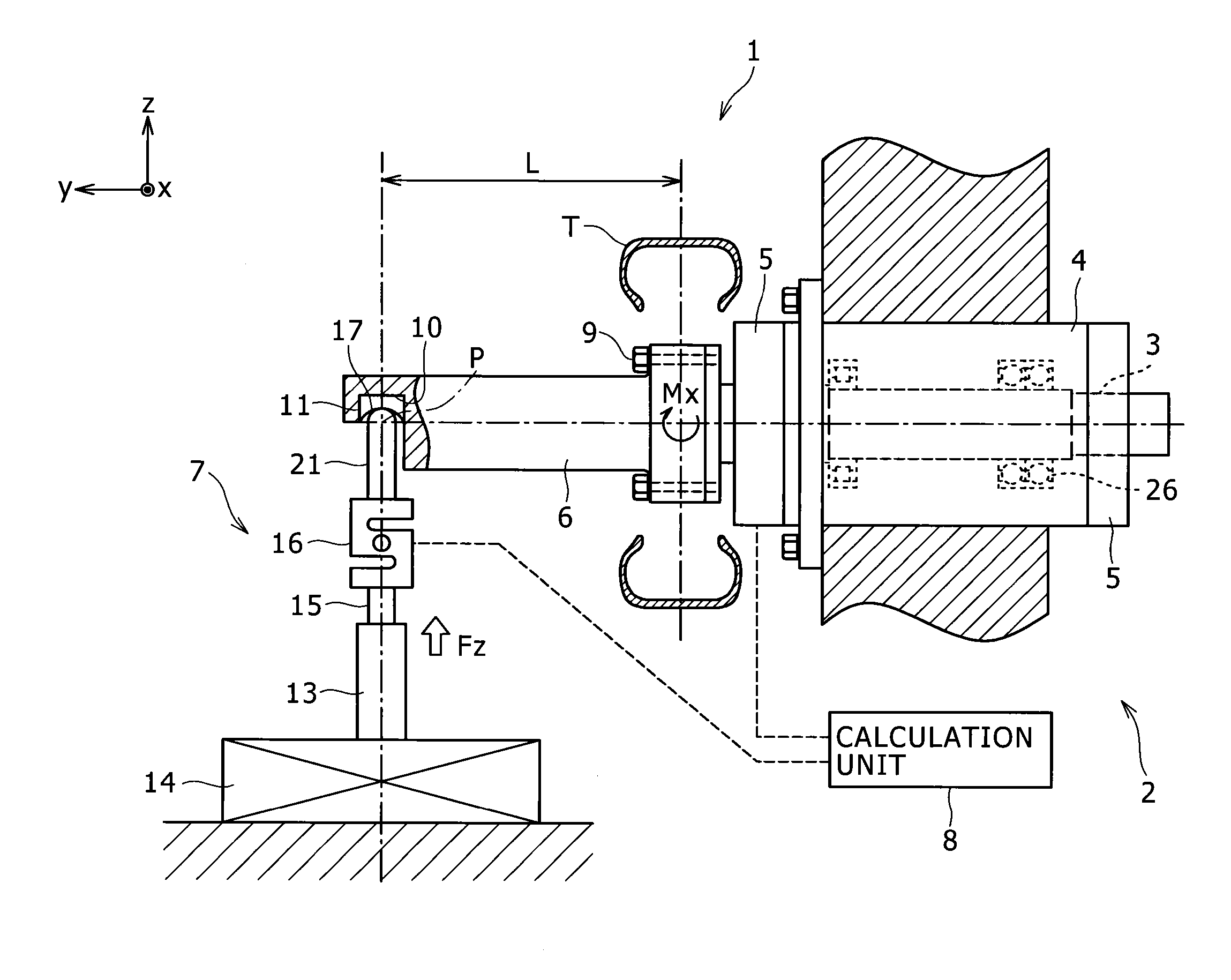
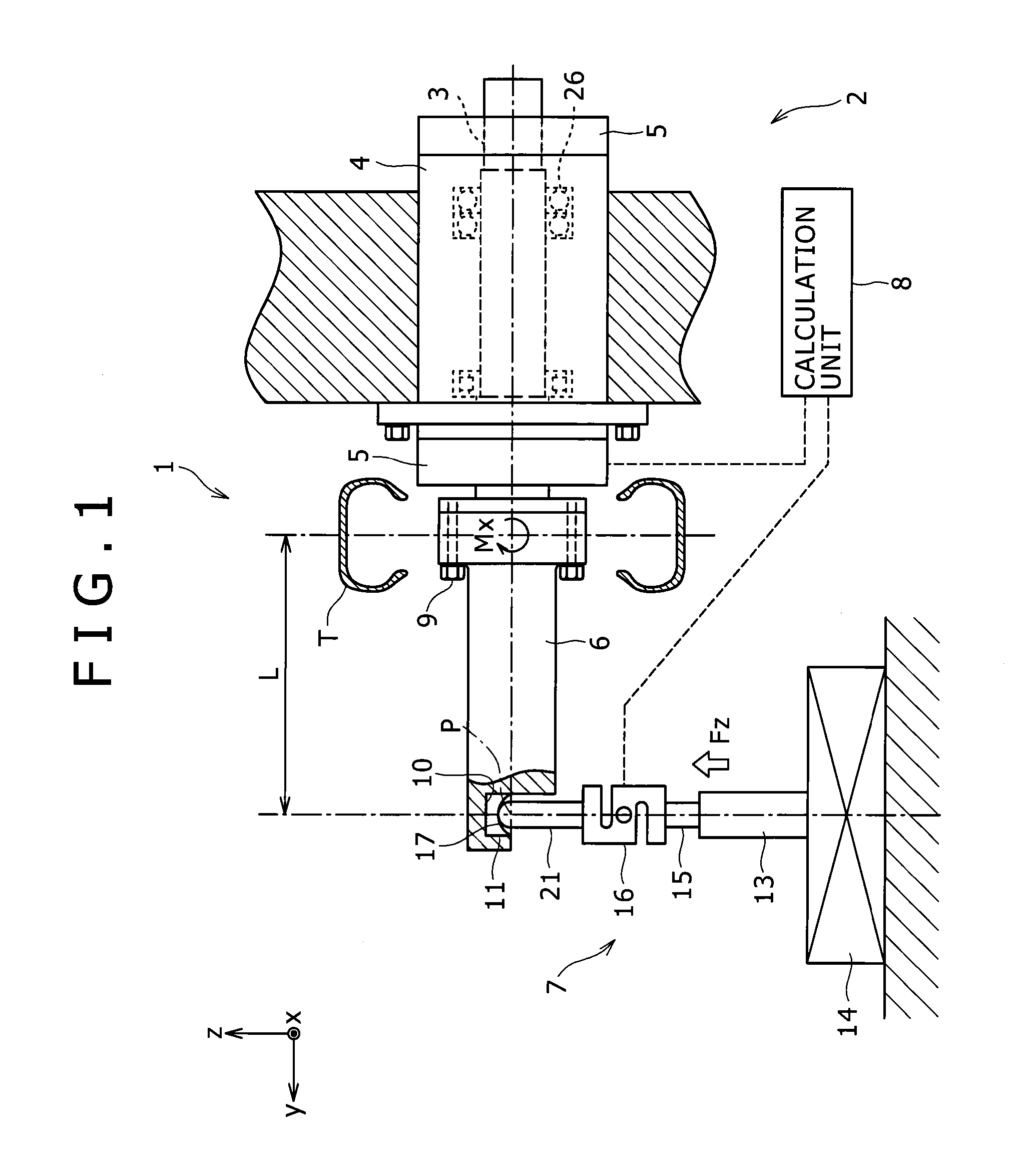
[0019]The tire testing apparatus 2 includes, as shown in FIG. 1, a spindle shaft 3 disposed with the center of its axis oriented along a lateral direction, a housing 4 for supporting the spindle shaft 3, and a multi-component force gauge 5 mounted on the housing 4. Bearings 26 are provided between the spindle shaft 3 and the housing 4. The bearings 26 support the spindle shaft 3 rotatably about the laterally oriented axis relative to the housing 4. A tire T may be mounted on an end (a left end) of the spindle shaft 3 using a not-illustrated rim or the like. The rotation of the spindle shaft 3 relative to the housing 4 can ca...

embodiment 2

[0075]Next, the moment calibrating apparatus 1 and the calibration method according to a second embodiment of the present invention will be described.

[0076]As shown in FIGS. 2 and 3, the moment calibrating apparatus 1 and the calibration method of the second embodiment are different from those of the first embodiment in that the moment calibrating apparatus 1 and the calibration method of the first embodiment relate to calibration of the multi-component force gauge 5 incorporated in the spindle whereas those of the second embodiment are to calibrate the multi-component force gauge 5 itself removed from the tire testing apparatus 2.

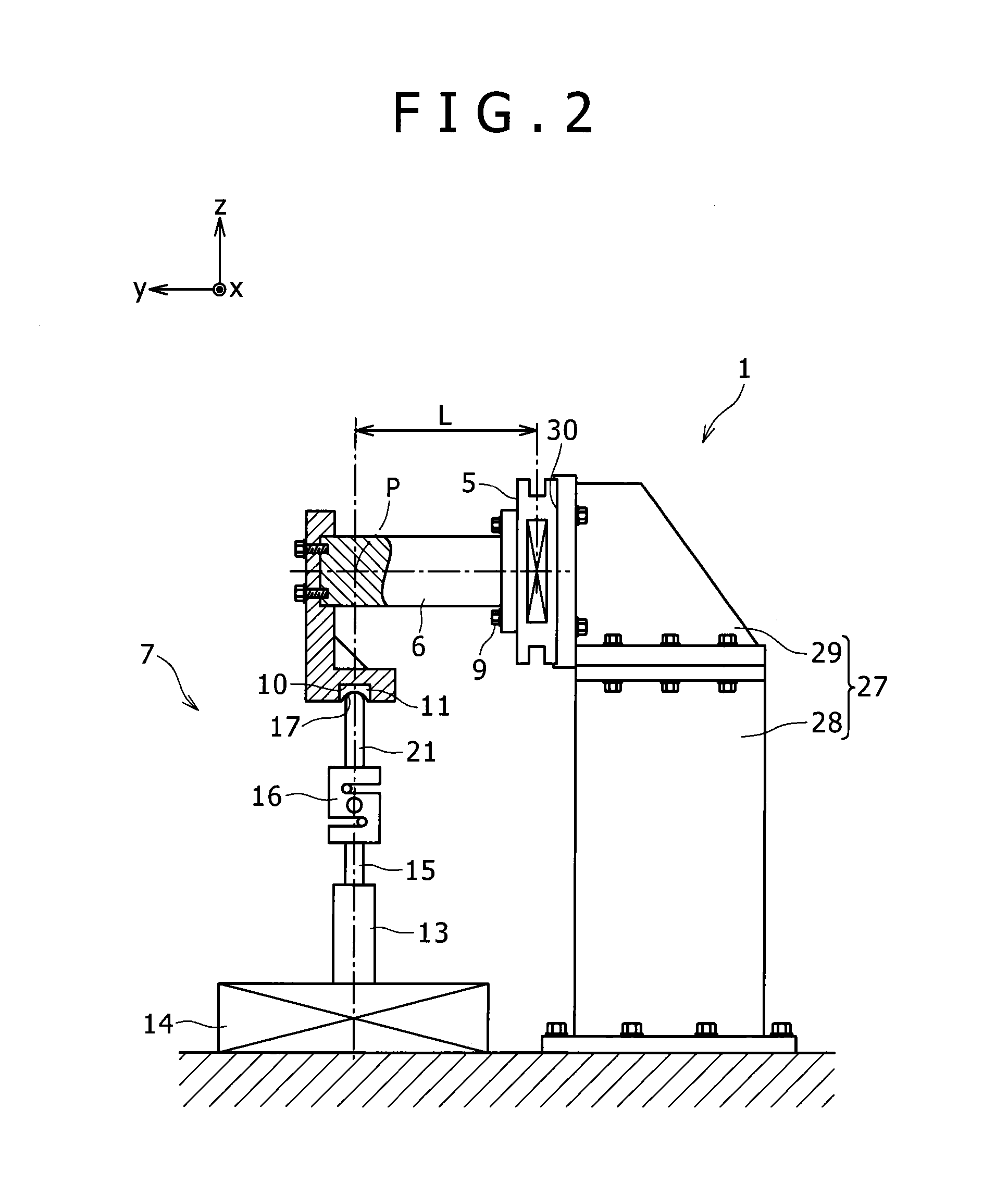
[0077]The moment calibrating apparatus 1 in the second embodiment is equipped with a support member 27 for fixing the multi-component force gauge 5 onto a stationary part such as a floor surface or a rigid base plate. The support member 27 is composed of a bottom member 28 fixed to the stationary part in a vertically oriented position and a top member 29 m...


PUM

PropertyMeasurementUnit
forceaaaaaaaaaa
forcesaaaaaaaaaa
weightaaaaaaaaaa

Abstract

A moment calibrating apparatus (1) is provided with an elongated force transmitting member (6) for transmitting a force applied to the end portion thereof to a multi-component force gauge (5), a load applying mechanism (7) for applying a load without changing the direction of the force along a direction perpendicular to said end portion, and a calculation unit (8) for calculating a true moment free from the effect of a perpendicular load on the basis of the moment value around the axis in the direction orthogonal to the perpendicular direction, measured by the multi-component force gauge (5) under the condition that said perpendicular load along the direction perpendicular to said end portion is applied by the load applying mechanism (7), wherein a moment calibration of the multi-component force gauge (5) is performed using said true moment calculated by the calculation unit (8).

Description

TECHNICAL FIELD[0001]The present invention relates to a moment calibrating apparatus for a multi-component force gauge and a method of moment calibration.BACKGROUND ART[0002]Tire testing apparatuses used for special inspection, evaluation, development and the like are equipped with multi-component force gages capable of measuring forces (Fx, Fy, Fz) along orthogonal three axes applied to tires rotating in contact with a road surface or moments (Mx, My, Mz) around the axes. Such a multi-component force gage is always calibrated when it is incorporated into the tire testing apparatus for the first time. Further, even after the incorporation into the tire testing apparatus, the multi-component force gauge is continually calibrated, for example, at predetermined regular time intervals to maintain its accuracy in measurement of the forces or the moments.[0003]For example, Patent Document 1 discloses a calibration method for calibrating a multi-component force gauge itself and a jig or a ...

Claims


Application Information

Patent Timeline
Patent Type & Authority Applications(United States)
IPC IPC(8): G01L25/00
CPCG01L25/00G01L25/003G01M1/045
Inventor SUMIMOTO, YUFUKUDA, TAKAYUKI
Owner KOBE STEEL LTD
Why Eureka
Try Eureka