Solar panel racking system

a solar panel and solar panel technology, applied in the direction of heat collector mounting/support, sustainable buildings, light and heating equipment, etc., can solve the problems of volatile cost of photovoltaic panels, achieve high storage capacity, rapid placement, alignment and adjustment, and reduce the effect of installation and maintenan

Inactive Publication Date: 2012-11-29
PEGASUS SOLAR
View PDF11 Cites 29 Cited by
  • Summary
  • Abstract
  • Description
  • Claims
  • Application Information

AI Technical Summary

Benefits of technology

[0005]Photovoltaic modules are described herein that are collapsible and angularly adjustable by hand, with particular embodiments including features that permit stacking or nesting of the modules for ease of storage and transport, and rapid placement, alignment, and adjustment for quick deployment, including the stable joining of multiple such modules in an array that makes maximal use of any given exposure area. These features can be achieved in a lightweight structure that does not require roof penetration. The structure includes a frame with the photovoltaic panel mounted inside the frame, and a leg joined to the frame at various angles relative to the frame, such that one of the two end edges of the frame can be placed at different heights relative to the opposing end edge of the frame, thereby holding the frame and the photovoltaic panel at any of different angles relative to the horizontal when the module is placed on a horizontal surface, one of the angles being zero relative to the horizontal or to the surface on which the module is placed, i.e., placing the panel being parallel to the surface. In certain embodiments, the joinder of the leg to the frame can be adjusted to achieve two or more angles above the horizontal (or surface), thereby offering a choice of tilt angles for the photovoltaic panel and a rapid switching among the various angles. The module can thus be placed on any horizontal surface, with or without securement to the surface or to the substructure supporting the surface, and yet the entire module, includi

Problems solved by technology

The cost of photovoltaic panels is volatile because of such factors as government subsidies, foreign competition, changes in the costs of materials, and advances in th

Method used


Image

  • Solar panel racking system
  • Solar panel racking system
  • Solar panel racking system

Examples


Embodiment Construction

[0026]While novel concepts of the invention herein are susceptible to numerous embodiments and implementations, they will be best understood by a detailed examination of certain specific embodiments. Such embodiments are depicted in the Figures and described below.

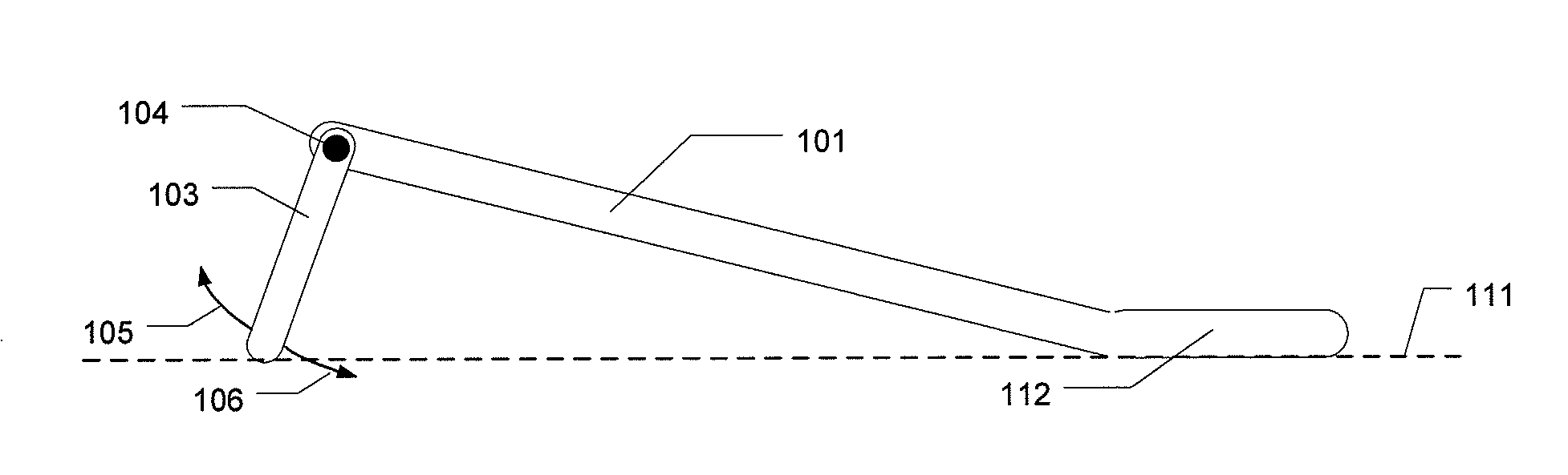
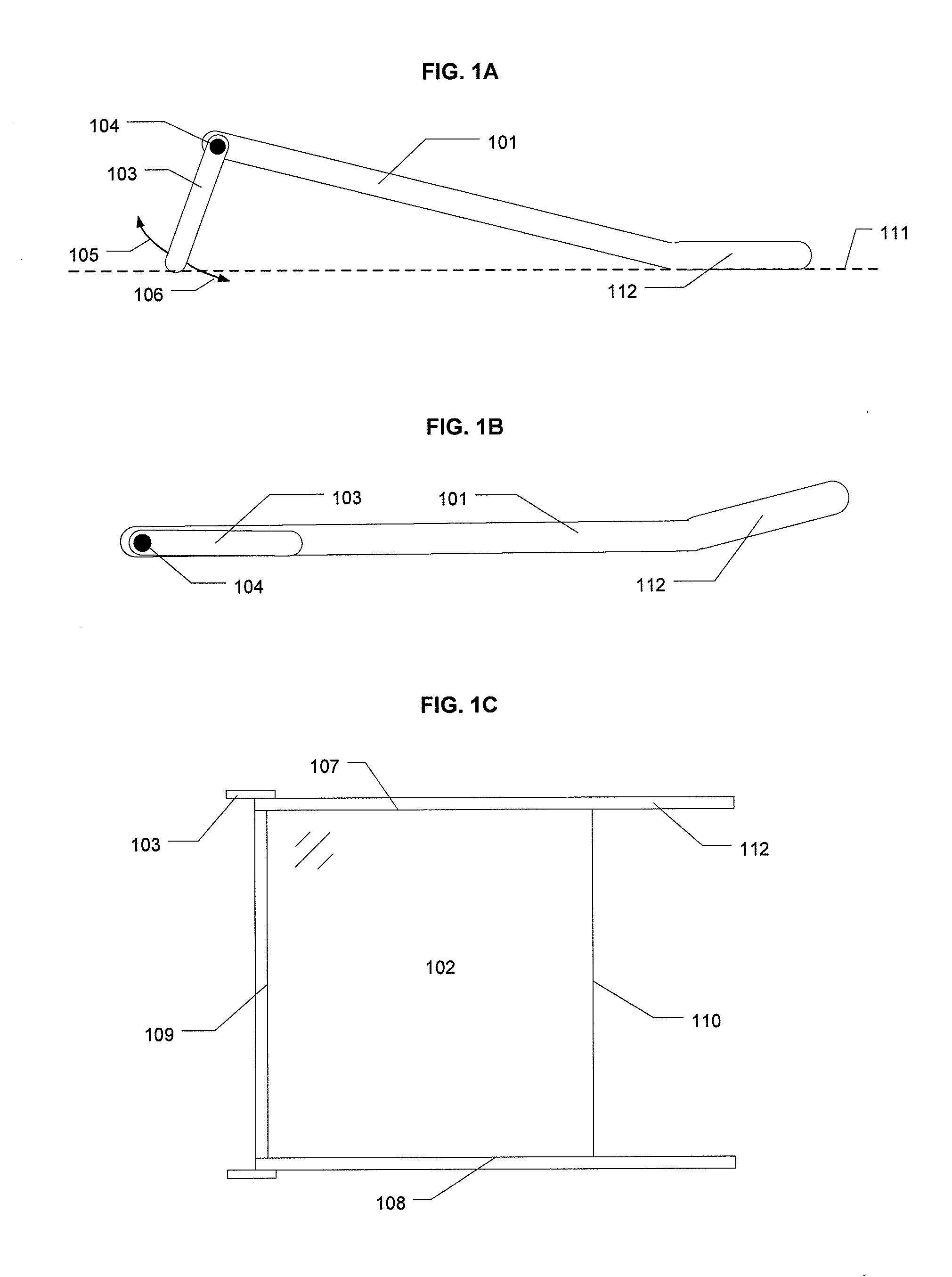
[0027]FIGS. 1A, 1B, and 1C are three views of a module that includes a frame 101 in which the flat, rectangular photovoltaic panel 102 (FIG. 1C) is mounted. The module also includes an articulating leg 103 that is pivotally attached to the frame at a pivot joint 104 along the directions of the arrows 105, 106 (FIG. 1A), or at least in the direction of one arrow 106. The photovoltaic panel 102 is rectangular and has a pair of lateral edges 107, 108 and a pair of end edges 109, 110, and the pivot joint 104 allows the leg 103 to rotate about an axis parallel to the end edges 109, 110. FIGS. 1A and 1B depict the leg 103 in two positions, the first position placing one end edge 109 of the panel at a greater height relative to t...


PUM


Abstract

Photovoltaic modules that are collapsible and angularly adjustable are made by mounting a photovoltaic panel in a frame, with a leg joined to the frame, the leg being manually adjustable to various angles, tilting the frame at various angles relative to the horizontal by simply lifting the frame. Certain embodiments also include interlocking features that join adjacent frames to form a rectangular array of modules.

Description

BACKGROUND OF THE INVENTION[0001]1. Field of the Invention[0002]This invention resides in the field of mounting structures for photovoltaic panels.[0003]2. Description of the Prior Art[0004]The cost of photovoltaic panels is volatile because of such factors as government subsidies, foreign competition, changes in the costs of materials, and advances in the technology of photovoltaics including the introduction of new materials and the replacement of costly materials with those that are cheaper or more readily available. These factors have affected the cost of manufacture, purchase, and installation of the panels, but they have also prompted the use of innovative marketing strategies, such as the leasing of photovoltaic modules rather than purchase and the limiting of customer charges to a periodic use fee without charging the customer for installation. One result of these innovations and variations is that the cost contributions other than those of the panels themselves have become ...

Claims


Application Information

Patent Timeline
IPC IPC(8): H01L31/045H02S30/20
CPCH01L31/02Y02E10/50Y02B10/12F24J2/523H02S20/24F24J2002/5277F24J2002/5279Y02E10/47H02S20/00F24J2/5264F24S25/10F24S25/70F24S2025/012F24S2025/013H02S20/30H02S30/20Y02B10/10
Inventor STEPHAN, ERICH KAI
Owner PEGASUS SOLAR
Why Eureka
Try Eureka