Eureka AIR delivers breakthrough ideas for toughest innovation challenges, trusted by R&D personnel around the world.

Apparatus for filling paint cartridges

Active Publication Date: 2012-11-29
TOYOTA JIDOSHA KK +1
View PDF14 Cites 4 Cited by
  • Summary
  • Abstract
  • Description
  • Claims
  • Application Information

AI Technical Summary

Benefits of technology

[0012]The invention provides a paint filling apparatus which fills a paint cartridge with a color paint selected from a plurality of paints of different colors, and which realizes a compact construction of the apparatus as a whole and reduction of the manufacturing cost while reducing the paint loss.
[0017]According to the invention, it is possible to provide a paint filling apparatus which fills a paint cartridge with the paint of a color selected from a plurality of paints, and which allows a reduction of the paint loss, and achieves a compact construction of the apparatus as a whole, and a reduction of the manufacturing cost.

Problems solved by technology

If a connecting portion, between the paint filling apparatus and a paint cartridge (an opening for supplying paint into the paint cartridge) is provided only at one site regardless of the color of paint, the paint loss (an amount of paint that is not filled into the paint cartridge but is discarded) increases.
Therefore, in a construction in which the connecting portion is provided only at one site, when a “color changing operation” regarding the paint in the paint cartridge is performed, the entire region in the supply channel from the paint supply source to the connecting portion needs to be washed, and the amount of paint remaining in the supply channel is discarded as a paint loss.
However, as for the paint filling apparatus equipped with paint supply portions separately for individual colors of paints, since a plurality of common manifold portions are disposed separately for each of colors of paints, the paint filling apparatus as a whole becomes large in size, requiring a large space for installation.
Besides, the overall cost for the paint filling apparatus is considerably high.

Method used


Image

  • Apparatus for filling paint cartridges
  • Apparatus for filling paint cartridges
  • Apparatus for filling paint cartridges

Examples


Embodiment Construction

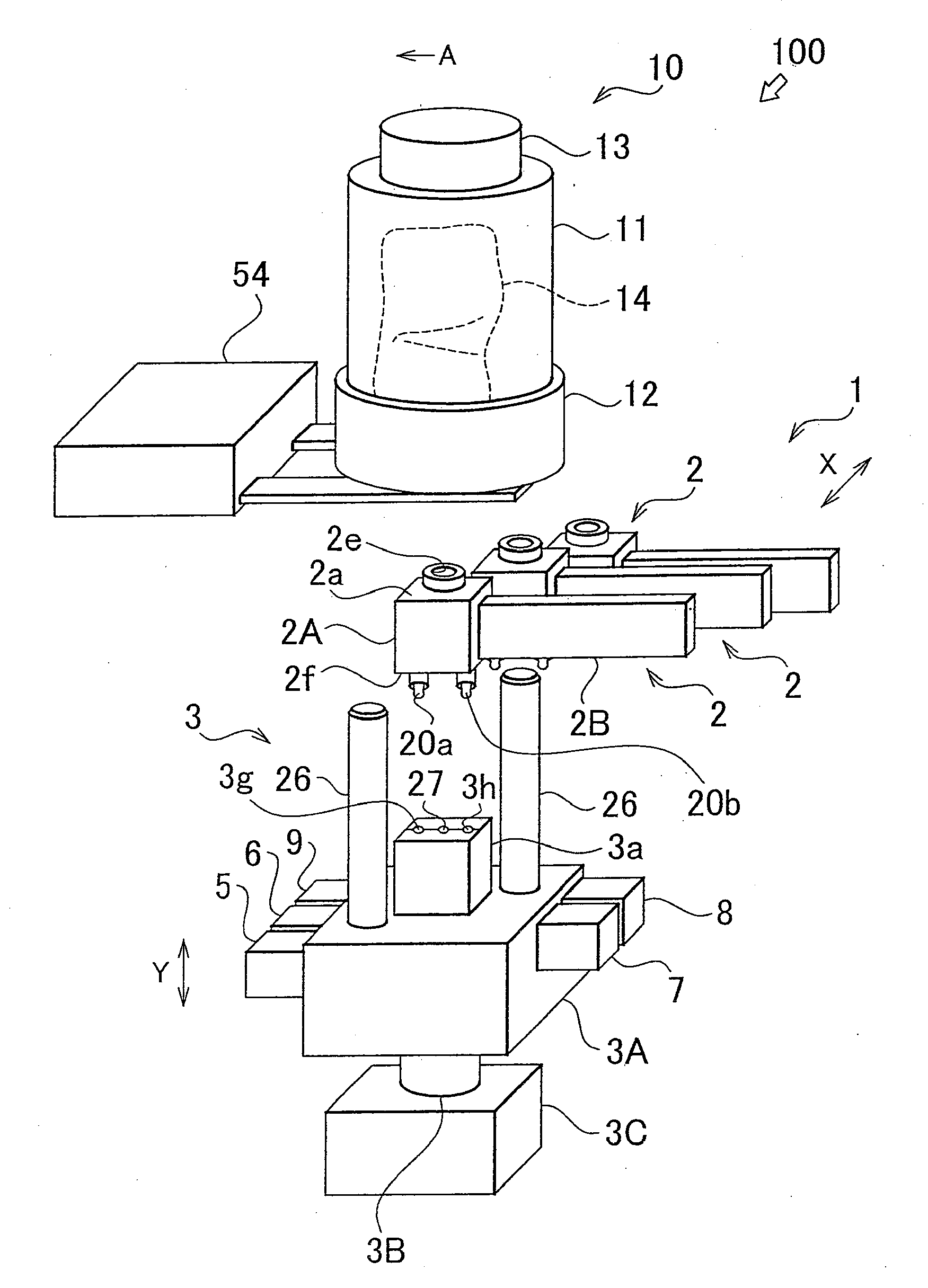
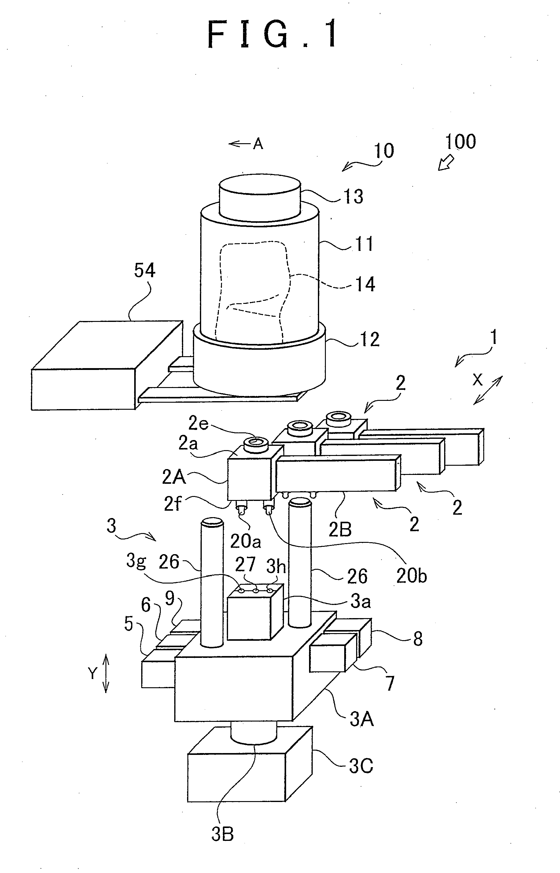
[0024][GENERAL CONSTRUCTION OF PAINT FILLING APPARATUS 1] Firstly, a general construction of a paint filling apparatus 1 in accordance with an embodiment of the invention will be described with reference to FIG. 1. Incidentally, for the sake of convenience in the following description, the up-down or vertical directions in FIG. 1 are defined as up-down or vertical directions regarding the paint filling apparatus 1, and the direction of an arrow A in FIG. 1 is defined as a forward direction.

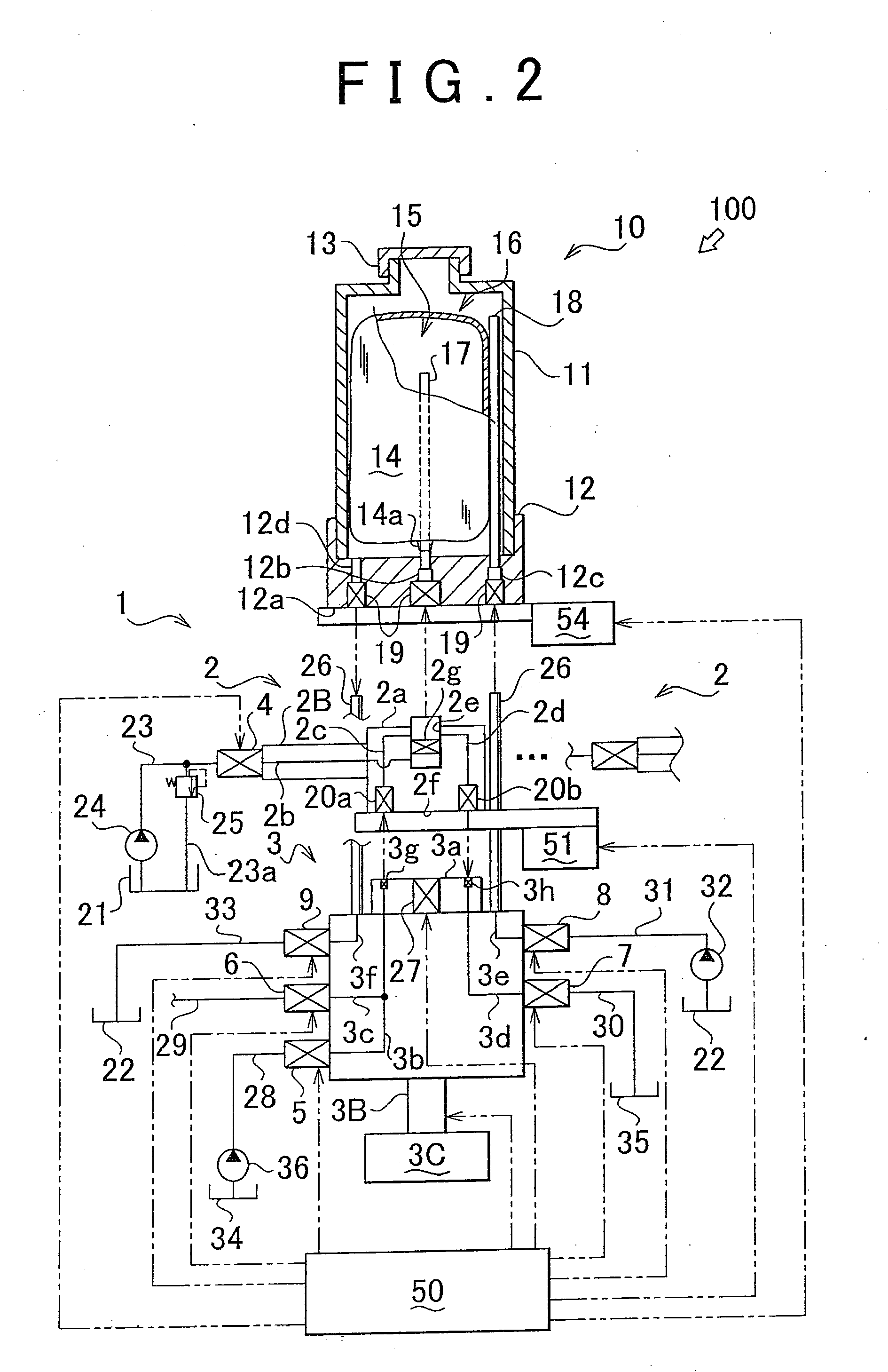
[0025]The paint filling apparatus 1 is constructed to be attachable to and detachable from a paint cartridge 10, and to fill an inside of the paint cartridge 1 with a paint of a color paint that is arbitrarily selected from a plurality of paints of different colors. The paint filling apparatus 1 is constructed mainly of a plurality of header portions 2 and one common manifold portion 3. Each header portion 2 and the common manifold portion 3 are attached to and detachable from each other. The head...


PUM

PropertyMeasurementUnit
Coloraaaaaaaaaa
Elongationaaaaaaaaaa

Abstract

A paint filling apparatus has a plurality of header portions, and one common manifold portion that is capable of supplying a cleaning liquid to each header portion. One side of each header portion is attachable to and detachable from a paint cartridge, and another side of each header portion is attachable to and detachable from the common manifold portion. Each header portion has a paint supply channel for filling a paint into the paint cartridge. The paint supply channel of each header portion is constructed of a piping member and a paint channel. An end portion of each header portion is linkable in communication with the inside of the paint cartridge, and another end portion thereof is linked in communication with a corresponding one of paint tanks that are provided separately for each of the paint colors. An intermediate portion of each paint supply channel is provided with a paint valve that controls the open-closed state of the upstream side of the paint supply channel.

Description

BACKGROUND OF THE INVENTION[0001]1. Field of Invention[0002]The invention relates to a technology of a paint filling apparatus that fills a paint into a paint cartridge for use in an electrostatic painting machine. More concretely, the invention relates to a technology for providing an economical and compact paint filling apparatus that is used to fill a paint cartridge with a paint of a color that is arbitrarily selected from a plurality of color paints.[0003]2. Description of Related Art[0004]Generally, the painting of bodies of motor vehicles and the like, due to its requirement for high painting quality, employs electrostatic painting machines that are excellent in the efficiency of adhesion of paint to painting surfaces, the smoothness of paint films after the painting process, etc. A widely known example of the electrostatic painting machines is a rotary atomizing head type painting machine. The rotary atomizing head type painting machine is equipped with a rotary atomizing he...

Claims


Application Information

Patent Timeline
IPC IPC(8): B65B3/04
CPCB05B12/1463
Inventor NABESHIMA, ATSUOTANI, SHINJIMORI, TAKANOBUYAMASAKI, ISAMUNAKANE, SHINICHIFUKUZAWA, KOJIHASUIKE, TOMOHIRO
Owner TOYOTA JIDOSHA KK
Why Eureka
Eureka Blog
Learn More