Control device and control method for transmission mechanism

Active Publication Date: 2012-11-29
JATCO LTD +1
View PDF13 Cites 9 Cited by
  • Summary
  • Abstract
  • Description
  • Claims
  • Application Information

AI Technical Summary

Benefits of technology

[0004]The present invention was developed to solve such a problem and aims to reduce a sense of incongruity given to a driver when a return is made from an idle stop control.
[0007]When the hydraulic pressure is supplied to the second clutch different from the first clutch to be engaged at startup and the second clutch is engaged in the case of a return from the idle stop control, a drive torque transmitted to an output shaft is reduced. Thus, even if an engine rotation speed temporarily exceeds an idle rotation speed as the engine is started in the case of a return from the idle stop control, a pushed feeling given to the driver can be reduced since the drive torque transmitted to the output shaft is reduced.
[0010]Contrary to this, according to the above aspects, it is possible to reduce a pushed feeling caused by a temporary increase of the engine rotation speed and reduce a sense of incongruity given to the driver by setting the second clutch in the slip interlock state where the second clutch is not completely engaged.

Problems solved by technology

A resulting drive torque is transmitted to an output shaft, thereby causing a shock, which raises the problem of giving a pushed feeling and a sense of incongruity to a driver.

Method used


Image

  • Control device and control method for transmission mechanism
  • Control device and control method for transmission mechanism
  • Control device and control method for transmission mechanism

Examples


first embodiment

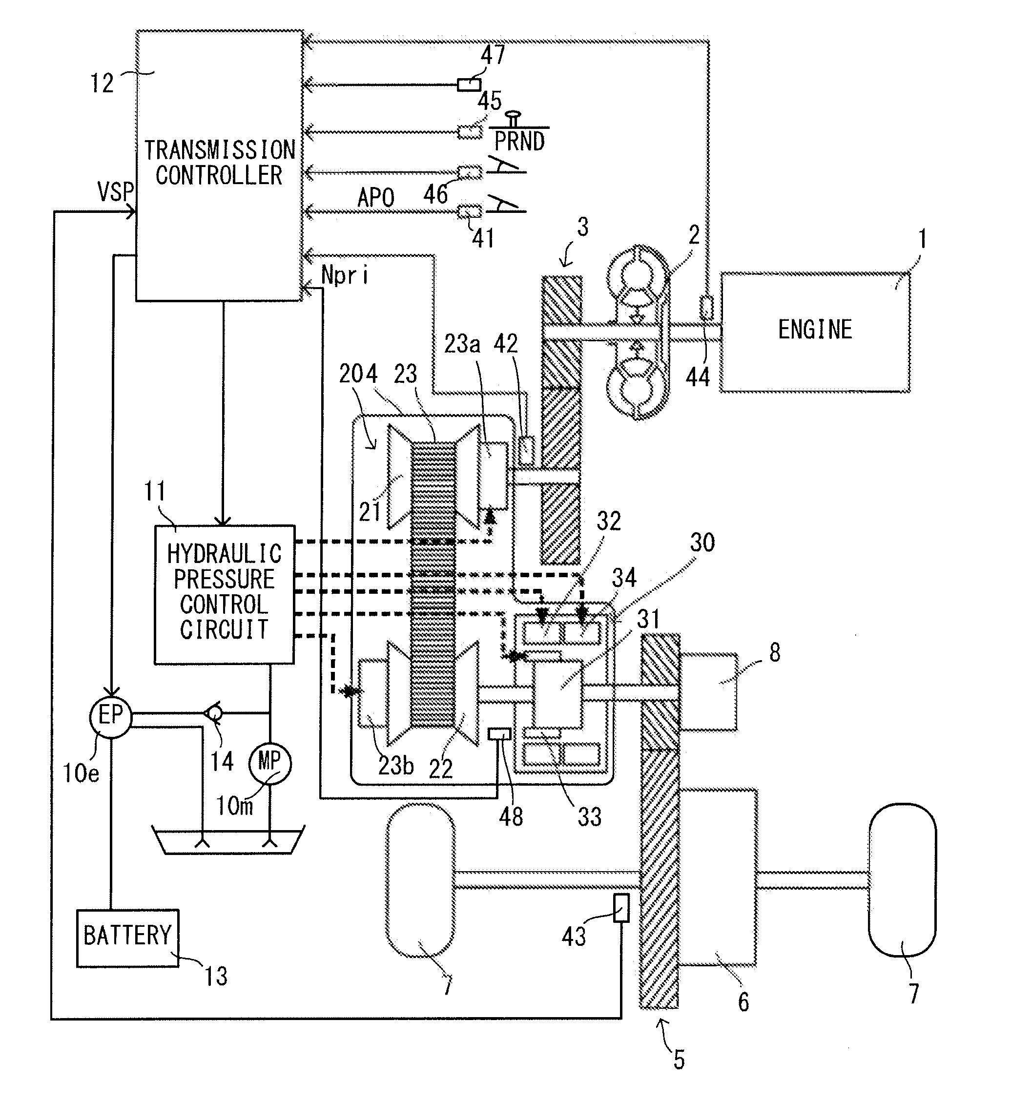
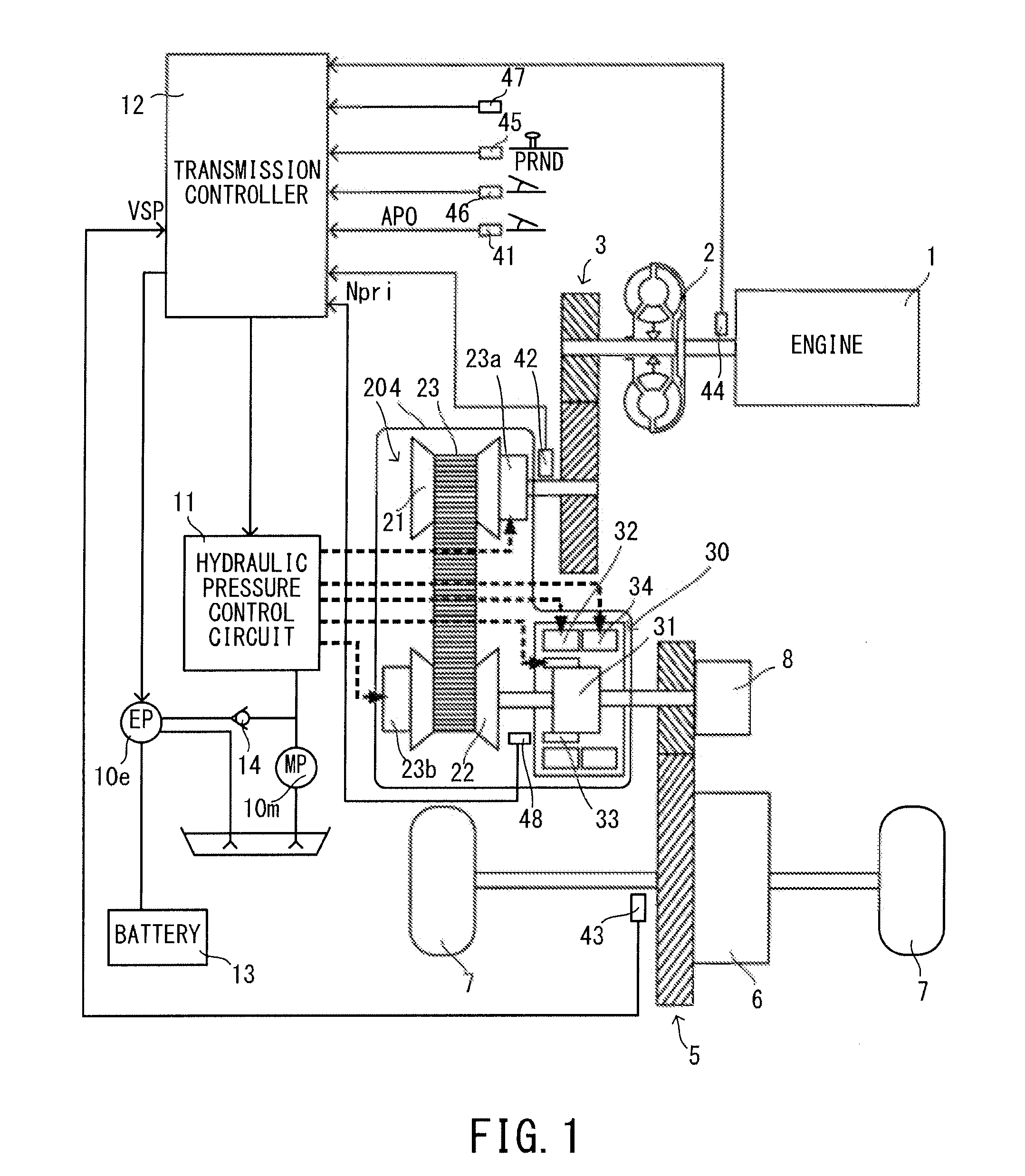
[0027]FIG. 1 is a schematic configuration diagram of a vehicle equipped with a control device for a transmission mechanism according to the present embodiment. This vehicle includes an engine 1 as a drive source. Output rotation of the engine 1 is transmitted to drive wheels 7 via a torque converter 2 with a lock-up clutch, a first gear train 3, a continuously variable transmission (hereinafter, merely referred to as a “transmission 4”), a second gear train 5 and a final speed reducer 6. The second gear train 5 includes a parking mechanism 8 for mechanically locking an output shaft of the transmission 4 in a parked state so as not to be able to rotate.

[0028]The vehicle includes a mechanical oil pump 10m which is driven using a part of power of the engine 1, an electrical oil pump 10e which is driven by an electric motor, a hydraulic pressure control circuit 11 which adjusts a hydraulic pressure from the mechanical oil pump 10m or the electrical oil pump 10e and supplies the adjusted...

second embodiment

[0122]Effects of the present invention are described.

[0123]By controlling the hydraulic pressure of the high clutch 33 so that the actual output torque T1out of the sub-transmission mechanism 30 monotonously increases with the predetermined upward gradient, it is possible to reduce a variation of the torque output from the sub-transmission mechanism 30 and reduce a pushed feeling given to the driver, a feeling of slowness at startup and a sense of incongruity given to the driver in the case of a return from the idle stop control.

[0124]By increasing the upward gradient of the target output torque T1o as the upward gradient increases, the decreased amount of the hydraulic pressure of the high clutch 33 per unit time can be increased. Thus, in the case of a return from the idle stop control, the output torque T1out of the sub-transmission mechanism 30 more quickly increases, wherefore it is possible to reduce a downward slide of the vehicle and improve vehicle startability.

[0125]Next, ...

third embodiment

[0163]Next, the case using this embodiment (third embodiment) is described. Also in FIG. 14, changes of the actual hydraulic pressure and the actual output torque when the response of the hydraulic pressure is slow are shown by broken line.

[0164]A return is made from the idle stop control at time t0 and the slip interlock release control is started at time t1.

[0165]Since [input torque T3×B−(input torque T3×B)′] becomes larger than the fourth predetermined value when the engine rotation speed Ne increases again at time t2, the instruction hydraulic pressure of the high clutch 33 is kept at the instruction hydraulic pressure in the last calculation. Thus, the vehicle that is once started does not decelerate. Further, the change of the actual output torque T1out decreases and a sense of incongruity given to the driver can be reduced when the response of the hydraulic pressure is slow.

[0166]When the changed amount of the engine rotation speed Ne decreases and the fourth predetermined va...


PUM


Abstract

In the case of a return from an idle stop control in which an engine is automatically stopped, a hydraulic pressure is so supplied that a low brake is set in a completely engaged state and a high clutch is set in a slip interlock state where the high clutch is not completely engaged.

Description

TECHNICAL FIELD[0001]The present invention relates to a control device and a control method for a transmission mechanism.BACKGROUND ART[0002]A conventional device which includes a mechanical oil pump and an electrical oil pump and in which a hydraulic pressure is supplied from the electrical oil pump to a gear corresponding to a starting shift position during an idle stop control is disclosed in JP2002-47962A.SUMMARY OF INVENTION[0003]However, in the above invention, an engine rotation speed temporarily increases to a rotation speed higher than an idle rotation speed when a return is made from the idle stop control and an engine restarts. A resulting drive torque is transmitted to an output shaft, thereby causing a shock, which raises the problem of giving a pushed feeling and a sense of incongruity to a driver.[0004]The present invention was developed to solve such a problem and aims to reduce a sense of incongruity given to a driver when a return is made from an idle stop control....

Claims


Application Information

Patent Timeline
IPC IPC(8): F16D25/10
CPCF16H61/061F16H61/20F16H2059/663F16H2312/14Y10T477/688F16H2061/205Y10T477/6895Y10T477/6403Y10T477/689B60Y2300/18016F16H61/02F16H61/06F02D29/02
Inventor WAKAYAMA, HIDESHITATEWAKI, KEICHISEKIYA, HIROSHITAGAMI, KOUTAROUTAKAHASHI, SEIICHIROTOHTA, YUZURUMATSUDA, TAKASHIMATSUMOTO, DAISUKE
Owner JATCO LTD
Why Eureka
Try Eureka