Pivot-Fit Frame, System and Method for Photovoltaic Arrays

Inactive Publication Date: 2012-11-29
SOLARCITY
View PDF8 Cites 123 Cited by
  • Summary
  • Abstract
  • Description
  • Claims
  • Application Information

AI Technical Summary

Benefits of technology

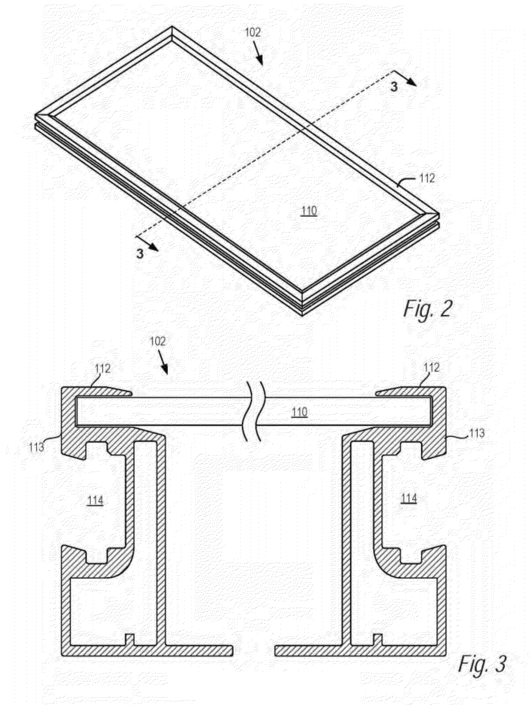
[0008]Disclosed herein is a system and method for quickly and easily assembling PV modules into a PV array in a sturdy and durable manner. In some embodiments, the PV modules may have a grooved frame where the groove is angled into the frame with respect to the planar surface of the modules. Various components may engage within the angled groove to assemble the PV modules into the PV array using what may be referred to as a pivot-fit connection between the components and angled groove. One type of component is a leveling foot which in some embodiments includes a foot mounted to a support surface and a coupling affixed to the foot. The coupling of the leveling foot may have a male component s

Problems solved by technology

Most PV module coupling systems require the time-consuming use of multiple small fasteners.
High part count and slow installation time is a major barrier to reducing PV system costs and adoption.
First, neither of these methods can adequately account for variations in the dimensions of PV modules and couplings due to manufacturing tolerances. PV modules typically vary by approximately ±0.10″ along the length and/or width dimension. When multiple modules are formed into columns in the north-south direction of the PV array, it is critical that any dimensional variations from one module in the column not carry forward to the next module in the column, as the dimensional variations will add up over the length of the column and result in significant dimensional differences from one column to the next. Likewise, the same problem exists with east-west rows of PV modules. This problem, frequently referred to as tolerance take-up, is solved in rail-based systems by spacing the modules in a column more or less from each other on top of mounting rails so that the next module in the column is properly positioned and/or by only linking modules to the rails along one axis, either east-west or north-south. However, in rail-free systems, a PV module is structurally connected to the next module in both the north-south direction and the east-west direction. Thus, if the seams between adjacent east-west modules do not line up because of compounded north-south dimensional variations, then it may be impossible to complete the installation of an array. In other systems compounded east-west variations may cause problems along the north-south axis. Press-fit and hook-typ

Method used


Image

  • Pivot-Fit Frame, System and Method for Photovoltaic Arrays
  • Pivot-Fit Frame, System and Method for Photovoltaic Arrays
  • Pivot-Fit Frame, System and Method for Photovoltaic Arrays

Examples


Embodiment Construction

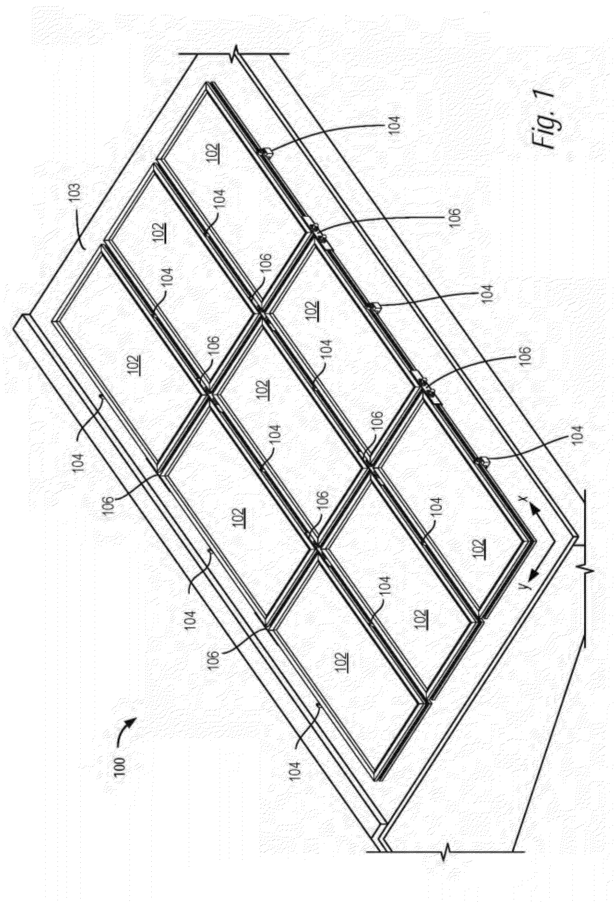
[0159]Referring now to FIG. 1, there is shown a perspective view of a PV array 100 including a plurality of PV modules 102 laid out in an x-y reference plane on a support structure 103. Mounting structure 103 is herein shown as including a planar surface, however it may be a structure with thickness, width, depth, and other dimension(s); in reference to any mounting structure, such as mounting structure 103, the height adjustment of a coupling described hereinafter is considered relative to any essential surface or essential plane, such as a top surface. The y-direction corresponds to the north-south dimension of the array, and the x-direction corresponds to the east-west direction. In the embodiment of FIG. 1, the reference plane is defined as being coextensive with a surface of the PV modules, when the PV modules are positioned in their final installed positions. However, in further embodiments, some of which are illustrated below, the reference plane may be above an upper surface...


PUM


Abstract

A system and apparatus are disclosed including PV modules having a frame allowing quick and easy assembling of the PV modules into a PV array in a sturdy and durable manner. In examples of the present technology, the PV modules may have a grooved frame where the groove is provided at an angle with respect to a planar surface of the modules. Various couplings may engage within the groove to assemble the PV modules into the PV array with a pivot-fit connection. Further examples of the present technology operate with PV modules having frames without grooves, or with PV modules where the frame is omitted altogether.

Description

CROSS REFERENCES[0001]The present application is a continuation-in-part of copending application Ser. No. 12 / 830,249, filed Jul. 2, 2010, which claims priority to Provisional Patent Application No. 61 / 270,122, filed Jul. 2, 2009; Provisional Patent Application No. 61 / 255,004, filed Oct. 26, 2009; and Provisional Patent Application No. 61 / 351,586, filed Jun. 4, 2010. This application also claims priority to U.S. Ser. No. 13 / 351,397, filed Jan. 17, 2012, which is a continuation of Ser. No. 12 / 594,935 filed Oct. 6, 2009, now U.S. Pat. No. 8,109,048, issued Feb. 7, 2012. This application also claims the benefit of U.S. Provisional Patent Application Ser. No. 61 / 445,042, filed Feb. 22, 2011. The foregoing applications are incorporated by reference in their entirety as if fully set forth herein.BACKGROUND[0002]Photovoltaic (PV) arrays are formed by mechanically linking together PV modules into an array. Most PV module coupling systems require the time-consuming use of multiple small faste...

Claims


Application Information

Patent Timeline
IPC IPC(8): H01L31/02
CPCF24J2/5211F24J2/5245F24J2/5247F24J2/5262F24J2/5264Y02B10/12H01L31/0422F24J2002/5292H02S20/00H02S20/23H02S20/24F16M13/02Y02E10/47F24S25/20F24S25/61F24S25/613F24S25/67F24S25/70F24S2025/02Y02B10/10Y02B10/20Y02E10/50E04D13/00H02S30/00
Inventor WEST, JOHN RAYMONDHUDSON, TYRUS HAWKES
Owner SOLARCITY
Why Eureka
Try Eureka