
Wearable Heads-up Display With Integrated Finger-tracking Input Sensor

a technology of input sensor and head-up display, which is applied in the direction of mechanical pattern conversion, instruments, cathode-ray tube indicators, etc., can solve the problems of affecting the accuracy of position detection

Inactive Publication Date: 2012-11-29
GOOGLE LLC
View PDF4 Cites 57 Cited by
  • Summary
  • Abstract
  • Description
  • Claims
  • Application Information

AI Technical Summary

Benefits of technology

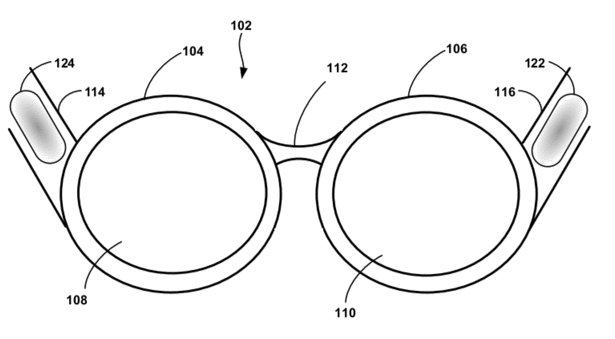
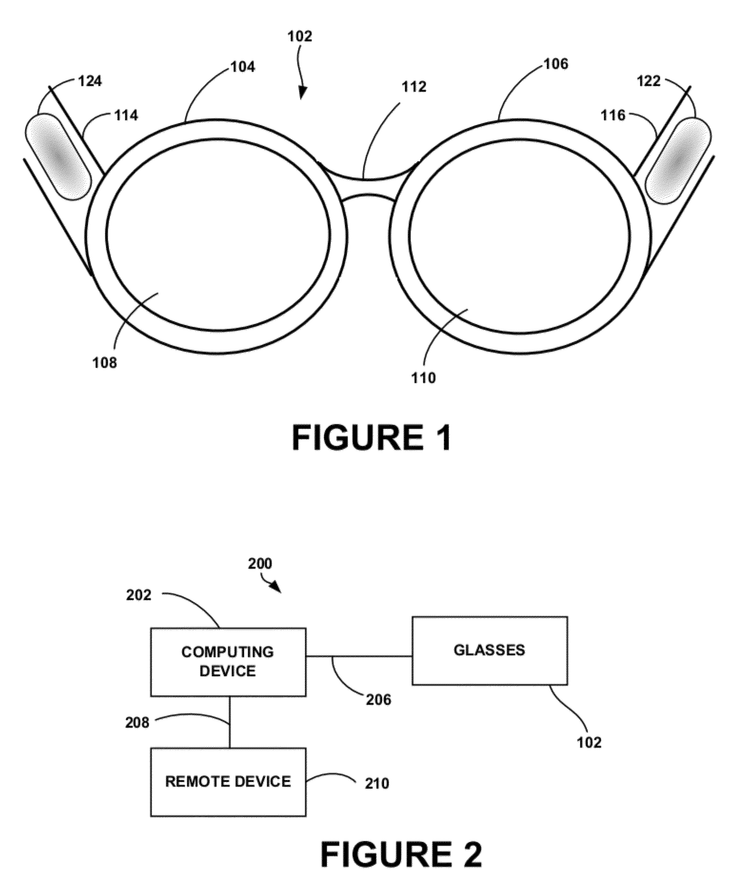
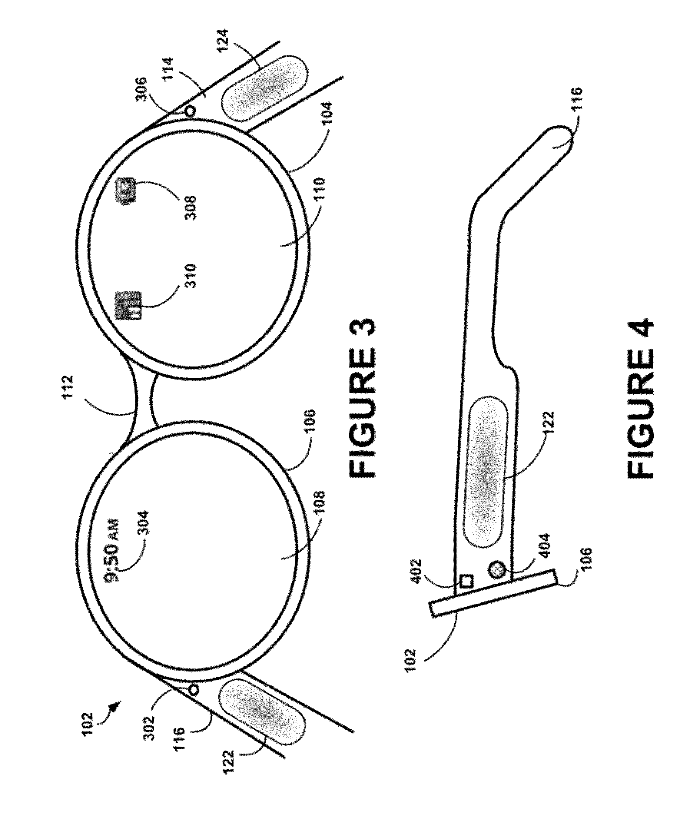
[0009]In one embodiment, the heads-up display may include two display elements coupled together via the wearable frame structure. In one example, the wearable frame structure may be a pair of glasses comprising two projections disposed on opposite sides of the two display elements (e.g., lenses), each projection extending away from each respective lens display element. The finger-operable input device may then be secured to the wearable frame structure via a first of the two projections. Furthermore, a second finger-operable input device may be secured to the wearable frame structure via a second of the two projections and configured to sense at least one of a position and movement of a finger along a planar direction relative to a surface of the second input device, and to provide corresponding input information to the processor. Such a configuration allows the same wearable heads-up display to be operated by both right-handed and left-handed users. Furthermore, the dual-input structure allows for an input system where the first finger-operable input device is configured to provide fine-motor input information to the processor and the second finger-operable input device is configured to provide gross-motor input information to the processor.
[0011]In another embodiment, the input device may include a touch-sensitive pad configured to sense at least one of a position and movement of a finger along a planar direction relative to a surface of the input device via capacitive sensing, resistance sensing, and / or via a surface acoustic wave (SAW) process. In yet another embodiment, the input device may be an optical imaging device and the surface of the optical imaging device a lens provided at an outer surface of the optical imaging device. By capturing images many times per second, the optical imaging device can accurately detect a position and movement of a finger along a planar direction relative to the lens surface of the input device.

Problems solved by technology

Further input could cause further updates to the display information or may cause the processor to execute other functions.
Due to the location of the finger-operable input device(s) on the stern of the glasses, the stems and / or input devices may block or hinder the peripheral vision of the user and / or block light from reaching a user's eyes.

Method used


Image

  • Wearable Heads-up Display With Integrated Finger-tracking Input Sensor
  • Wearable Heads-up Display With Integrated Finger-tracking Input Sensor
  • Wearable Heads-up Display With Integrated Finger-tracking Input Sensor

Examples


Embodiment Construction

[0024]in the following detailed description, reference is made to the accompanying figures, which form a part hereof. In the figures, similar symbols typically identify similar components, unless context dictates otherwise. The illustrative embodiments described in the detailed description, figures, and claims are not meant to be limiting. Other embodiments may be utilized, and other changes may be made, without departing from the spirit or scope of the subject matter presented herein. It will be readily understood that the aspects of the present disclosure, as generally described herein, and illustrated in the figures, can be arranged, substituted, combined, separated, and designed in a wide variety of different configurations, all of which are explicitly contemplated herein.

[0025]The methods and systems disclosed herein generally relate to wireless directional identification and communication between wearable heads-up displays. First, examples of wearable heads-up displays will be...


PUM


Abstract

Disclosed are systems, methods, and devices for interfacing with a wearable heads-up display via a finger-operable input device. The wearable heads-up display may include a display element for receiving and displaying display information received from a processor, and may also include a wearable frame structure supporting the display element and having a projection extending away from the display element. The projection may be configured to secure the heads-up display to a user's body in a manner such that the display element is disposed within a field of view of the user. A finger-operable input device secured to the wearable frame structure is configured to sense at least one of a position and movement of a finger along a planar direction relative to a surface of the input device, and to provide corresponding input information to the processor.

Description

CROSS REFERENCE TO RELATED APPLICATION[0001]The present application claims priority to U.S. patent application Ser. No. 13 / 115,430, filed on May 25, 2011, the entire contents of which are herein incorporated by reference.BACKGROUND[0002]Unless otherwise indicated herein, the materials described in this section are not prior art to the claims in this application and are not admitted to be prior art by inclusion in this section.[0003]Various technologies can be utilized to display information to a user of a system. Some systems for displaying information may utilize “heads-up” displays. A heads-up display can be incorporated into a pair of goggles, glasses, a headband, a helmet, or other such device that the user can wear. A heads-up display is typically positioned near the user's eyes and calibrated and / or aligned to the user's field of view to allow the user to review displayed information with little or no head movement. The display may also be transparent or translucent, allowing ...

Claims


Application Information

Patent Timeline
Patent Type & Authority Applications(United States)
IPC IPC(8): G06F3/01G06F3/045G06F3/043G06F3/044
CPCG02B27/017G02B2027/0178G06F3/03547G02B2027/0187G06F2203/0339G02B2027/0118G02B27/01
Inventor CHI, LIANG-YUPRADA GOMEZ, LUIS RICARDORYSKAMP, ROBERT ALLENMAVINKURVE, SANJAY G.
Owner GOOGLE LLC
Learn More