Device for removing a fluid from a vial

a technology for removing fluids and vials, which is applied in the field of devices for removing fluids, can solve the problems of chemically modified contents, gas, oxygen from the air, and leaking through seals, etc., and achieves the effects of unintentional spillage of fluids, incorrect manipulation, and gas leaking through seals

Active Publication Date: 2012-11-29
MEDMIX SWITZERLAND AG
View PDF6 Cites 83 Cited by
  • Summary
  • Abstract
  • Description
  • Claims
  • Application Information

AI Technical Summary

Benefits of technology

[0010]The present invention provides an adapter-like device for removing a fluid from at least one container sealed with a closure that can be punctured which allows the container to be stored on the device without unintentionally opening the container.
[0018]Each of the catch structures is preferably designed as follows: the container holder has a preferably at least partially cylindrical jacket wall. The first catch structure and the second catch structure each have a spring arm formed in the jacket wall, at the free end of which a catch lug is formed extending into the interior of the jacket wall. This allows very simple and cost-effective production. The catch structures are preferably offset, more particularly offset by approx. 180° with regard to the circumferential direction of the jacket wall, i.e. they are diametrically opposite each other in order to take up as little space as possible with as great stability of the container holder as possible. However, in relation to the circumferential direction of the jacket wall, the first catch structure and the second catch structure can be arranged directly next to each other. In the circumferential direction the two catch structure are then only separated from each other with an air gap. Preferably the catch lugs each have an oblique surface, the surface normal of which on the one hand points in the opposite direction to the direction of insertion of the container into the container holder, and on the other hand is inclined towards a longitudinal axis defined by the jacket wall.

Problems solved by technology

However, it is often problematical to store flowable substances for a longer period in plastic applicators, as on the one hand the substances can chemically react with the plastic, and on the other hand there is a risk that gas, in particular oxygen from the air, can diffuse though the walls of the applicator or through seals and chemically modify the content.
However, as the injection needle poses a potential risk of injury to the user and as sterility of the injection needle must be maintained during administration, any manipulations with the injection needle before the actual administration should be avoided.
However the simultaneous mounting of the device on the vial and puncturing of the septum can lead to incorrect manipulations, more particularly unintentional spilling of the fluid contained in the vial.
These filling systems are used, for example, when two components of a medicinal product have to be mixed with each other prior to application, but cannot be stored in the mixed state.
However, known devices are not generally suitable for storing the vial directly on the device as accidental puncturing of the septum of a vial cannot be ruled out during transportation or when being handled.
However, these devices have a relatively complex, multiple-part, structure and are therefore costly to manufacture.

Method used


Image

  • Device for removing a fluid from a vial
  • Device for removing a fluid from a vial
  • Device for removing a fluid from a vial

Examples


first embodiment

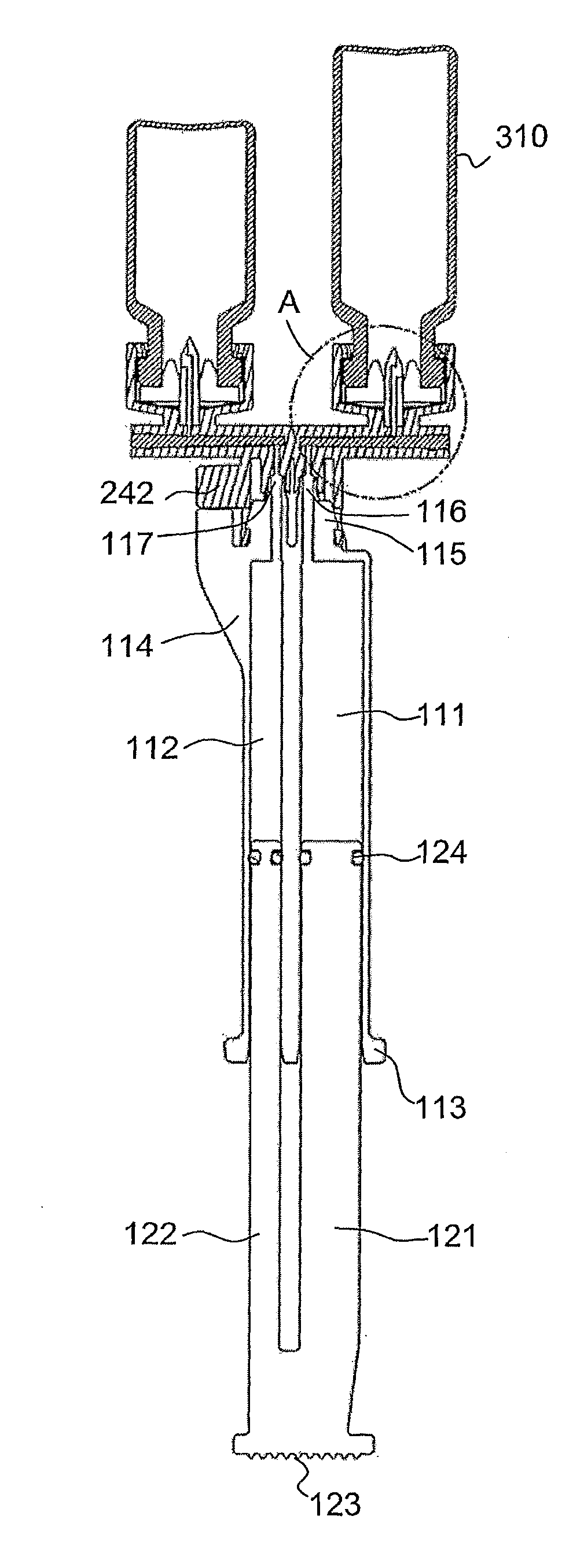
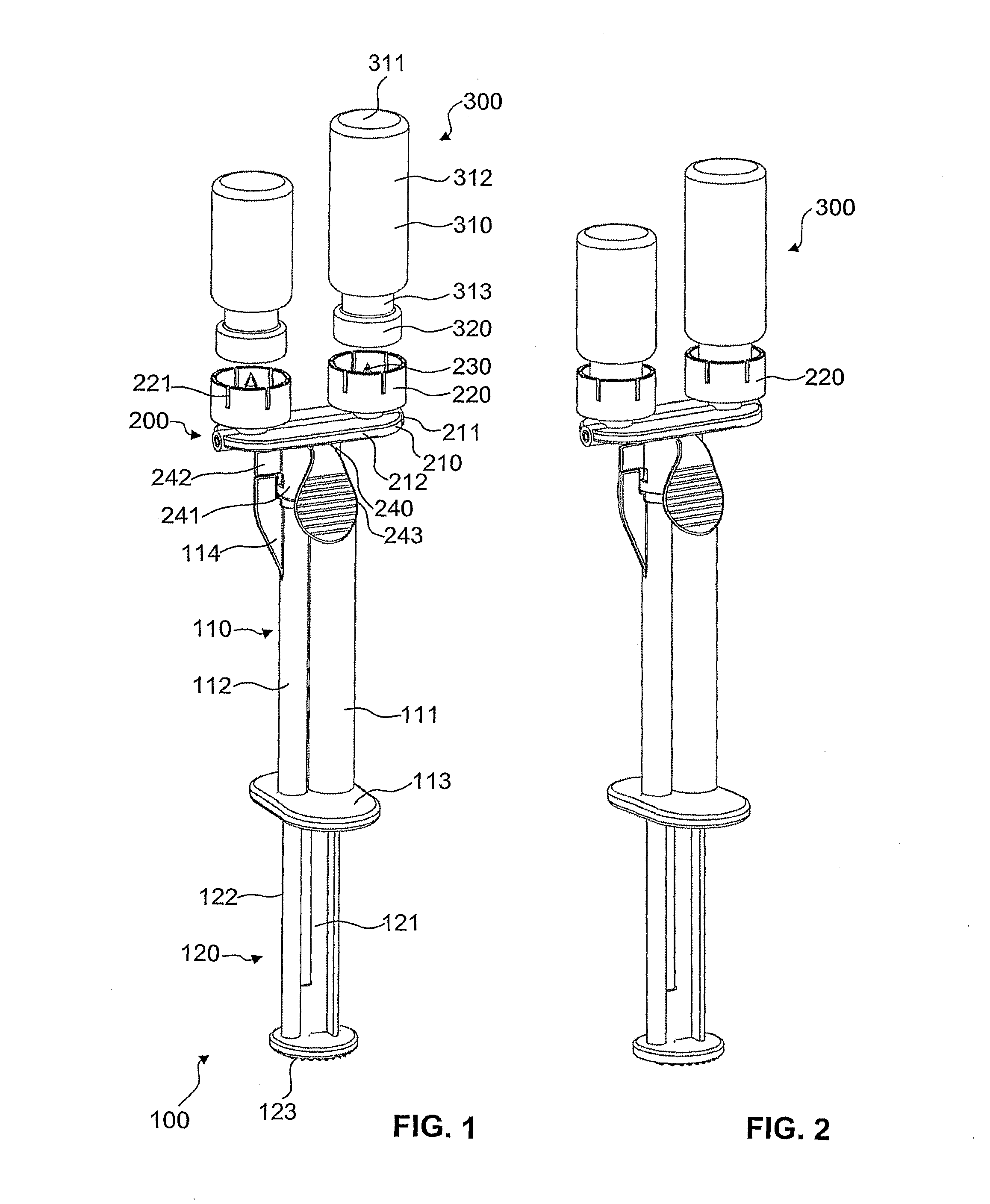
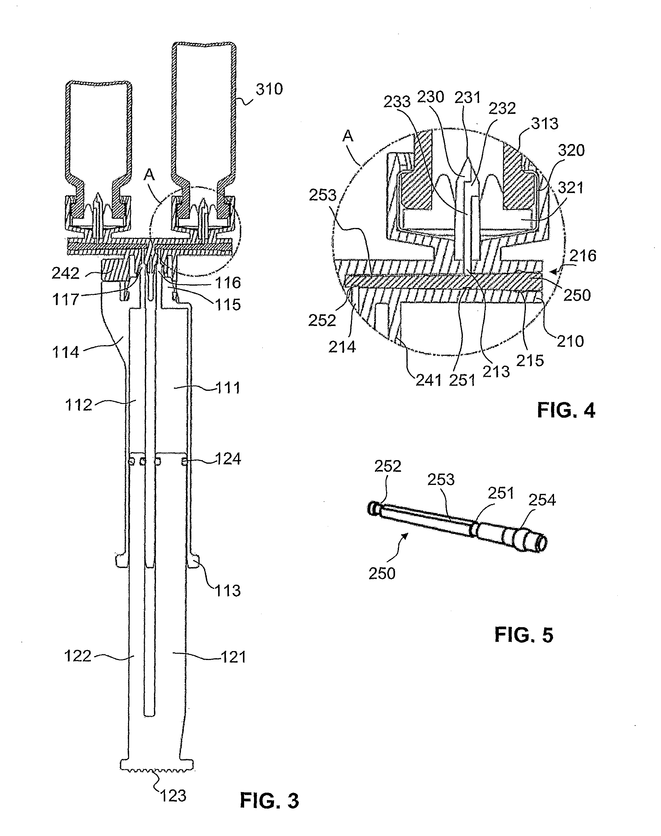
[0052]In FIGS. 6 and 8 a device in accordance with the invention is shown, which is designed to remove a fluid from at least one container sealed with a closure that can be punctured. This embodiment in accordance with the invention differs from the filling device in FIGS. 1 to 5 through the design of the container holders. More particularly, the manner in which the vials are held in the container holder is different.

[0053]The container holders 260 are here chimney-like, cylindrical structures which are of sufficient length to hold the entire container in terms of length. Whereas the container holders shown FIGS. 1 to 4 were produced in one piece with the basic body 210, the container holders 260 of the embodiment in FIGS. 6 to 8 are produced separately from the basic body 210 and connected to it by way of a suitable connection, e.g. a welded connection.

[0054]In the embodiment in FIGS. 6 to 8 each inlet opening 213 in the basic body has a larger diameter than in the filling device i...

second embodiment

[0058]In FIGS. 9 to 11b a filling device 270 in accordance with the invention is illustrated. In this embodiment the filling device 270 has a basic body 271 with only one container holder 272 and serves to fill an applicator 280 with a fluid from a container 300. Here the applicator 280 is in the form of a single syringe which has an applicator body 281 with a reservoir 282 and plunger 283 which can be moved therein.

[0059]The container holder 272 into which here a container 300 in the form of a vial can be inserted, has a circular base 276 from which over an angle range of approximately 270° a jacket wall extends upwards. The jacket wall 273 is partially cylindrical in the section facing the base 276 and thereby defines a longitudinal axis of the filling device 270. In an end area arranged at a distance from the base 276 the jacket wall 273 is however circumferentially designed, i.e. cylindrically. The jacket wall 273 thus has an essentially rectangular window opening which is defin...


PUM


Abstract

The invention relates to a device for removing a fluid from at least one container (300), from a vial for example, said container being closed by a closure (320) that can be punctured. The device comprises a base body (271) with a container receiving portion (272) and a hollow needle-like puncturing organ (277) in order to puncture the closure (320) of the container (300) in a removal position of the container (300). The aim of the invention is to enable mounting the container on the device without unintentionally puncturing the closure. This is achieved in that detent structures (274, 275) are provided which retain the container (300) on the device in a removal position and in a mounting position which is different from said removal position. Such a device can be used in particular to fill an applicator (280) with one or more fluid reservoirs from one or more vitals.

Description

TECHNICAL FIELD[0001]The present invention relates to a device for removing a fluid from at least one container, closed by means of a seal that can be punctured, e.g. a vial with a septum seal. In particular the invention relates to a device for filling an applicator with at least one fluid reservoir from one or more vials.PRIOR ART[0002]Particularly in medicine, but also in other technical fields, applicators such as syringes are often used to discharge and apply flowable substances in a controlled and dosed manner. The substances can for example be medicinal products or adhesives for medical or technical applications. A conventional syringe usually has at least one reservoir which holds a flowable substance. This substance is discharged through a distal outlet by means of plunger pushed into an open, proximal end of the reservoir. For subcutaneous or intravenous administration to a patient, for example, these syringes can have an injection needle which is in fluidic connection wit...

Claims


Application Information

Patent Timeline
Patent Type & Authority Applications(United States)
IPC IPC(8): A61J1/20
CPCA61J1/2096A61J2001/2013A61J2001/2058A61J2001/2055A61J2001/2051A61J1/201A61J1/2013A61J1/2051A61J1/2055A61J1/2058A61J1/2089
Inventor BREM, WILLIAMKAYSER, RALPH EGONGRETER, ANDY
Owner MEDMIX SWITZERLAND AG
Why Eureka
Try Eureka