System and Method for Using Multiple Detectors

a detector and detector technology, applied in the field of ophthalmic surgery, can solve the problems of new problems instead of correcting existing ones, affecting the patient's sight, and presenting an incomplete frame of reference for the eye,

Inactive Publication Date: 2012-11-29
TECHNOLAS PERFECT VISION
View PDF3 Cites 12 Cited by
  • Summary
  • Abstract
  • Description
  • Claims
  • Application Information

AI Technical Summary

Benefits of technology

[0007]Preferably, three separate detector units are provided to obtain both anatomical data and refractive data about the eye. One of the detector units (i.e. a first detector unit) is used to obtain anatomical data about the eye in two-dimensions (x-y directions). As envisioned for the present invention, this can be done by taking a video or a still image of the eye using a camera. Another detector unit (i.e. a second detector unit) is used to obtain additional anatomical data of the eye in a third dimension (z-direction). Imaging methods appropriate for providing this type of third-dimension data include the following: Optical Coherence Tomography (OCT), Scheimpflug imaging, confocal imaging, two-photon imaging, or ultrasound imaging. Together with the two-dimensional image from the first detector unit and z-direction information taken in an orthogonal direction to the two-dimensional image, a three-dimensional frame of reference can be created using data from the first and second detector units. Another detector unit (i.e. a third detector unit) is included in the system of the present invention to provide additional information for the planning of the treatment and for refining the three-dimensional frame of reference. In particular, this third detector unit is preferably a wavefront analyzer that can be used to generate refractive data about the eye. Alternatively, the third detector unit can be used to develop additional structural information about the eye. For instance, instead of a wavefront analyzer, this third detector unit may be an instrument for identifying a corneal topography for the eye, or it may create other types of images that are appropriate for the particular ophthalmic procedure being conducted. For all data sets, a same reference point is identified that can be located anywhere in / on the eye that would be visible in the video or still image produced by the first detector unit. Importantly, all data sets must share at least one common reference point. This is done to ensure all detector units, at least partially, map the same areas (volumes) of the eye, and that these areas (volumes) can be interrelated.
[0008]In an operation of the present invention, the plurality of detector units is activated to produce a respective plurality of data sets. Of these, one data set will establish a two-dimensional image of the eye that can be used to identify a reference point and for centration of the laser unit. In detail, centration can occur via one of three ways: (1) automatic pupil detection, (2) detecting a Purkinje reflex, or (3) detecting a reflection from the macula of the eye. Another data set can include measurements that are orthogonal to the two-dimensional image. Together these data sets can be used to produce a three-dimensional frame of reference. As indicated above, yet another data set pertaining to optical characteristics of the eye can be produced to complement and refine the three-dimensional frame of reference. Once all data sets are received at the computer, a computer program compiles all three of the data sets to produce a three-dimensional frame of reference. As noted above, a common reference point is essential to allowing the computer program to line up all data sets for a complete and accurate image of the eye. At this point, a selected procedure can be loaded into the computer for use with the three-dimensional frame of reference. The procedure is then forwarded from the computer to the electronic controller which activates the laser unit. During the procedure, at least one detector unit continues to monitor the eye and update the frame of reference to account for any anatomical or refractive changes induced by the laser procedure.

Problems solved by technology

Mistakes during these types of procedures can have dire consequences to the sight of a patient.
More specifically, an improperly directed laser beam can cause significant damage to various areas of the eye and lead to new problems instead of correcting existing ones.
Yet, when used individually, many of these devices offer an incomplete frame of reference for the eye.
Furthermore, many of the devices do not update an image once an ophthalmic procedure is in progress.
This inability to provide updated data can be detrimental because the anatomy of the eye may well undergo significant changes during an ophthalmic procedure.
Consequently, the laser eye surgeon may be relying on incomplete or inaccurate data while operating on a patient.
When data is inaccurate, the risk of serious damage to the eye of a patient increases significantly.

Method used


Image

  • System and Method for Using Multiple Detectors
  • System and Method for Using Multiple Detectors
  • System and Method for Using Multiple Detectors

Examples


Embodiment Construction

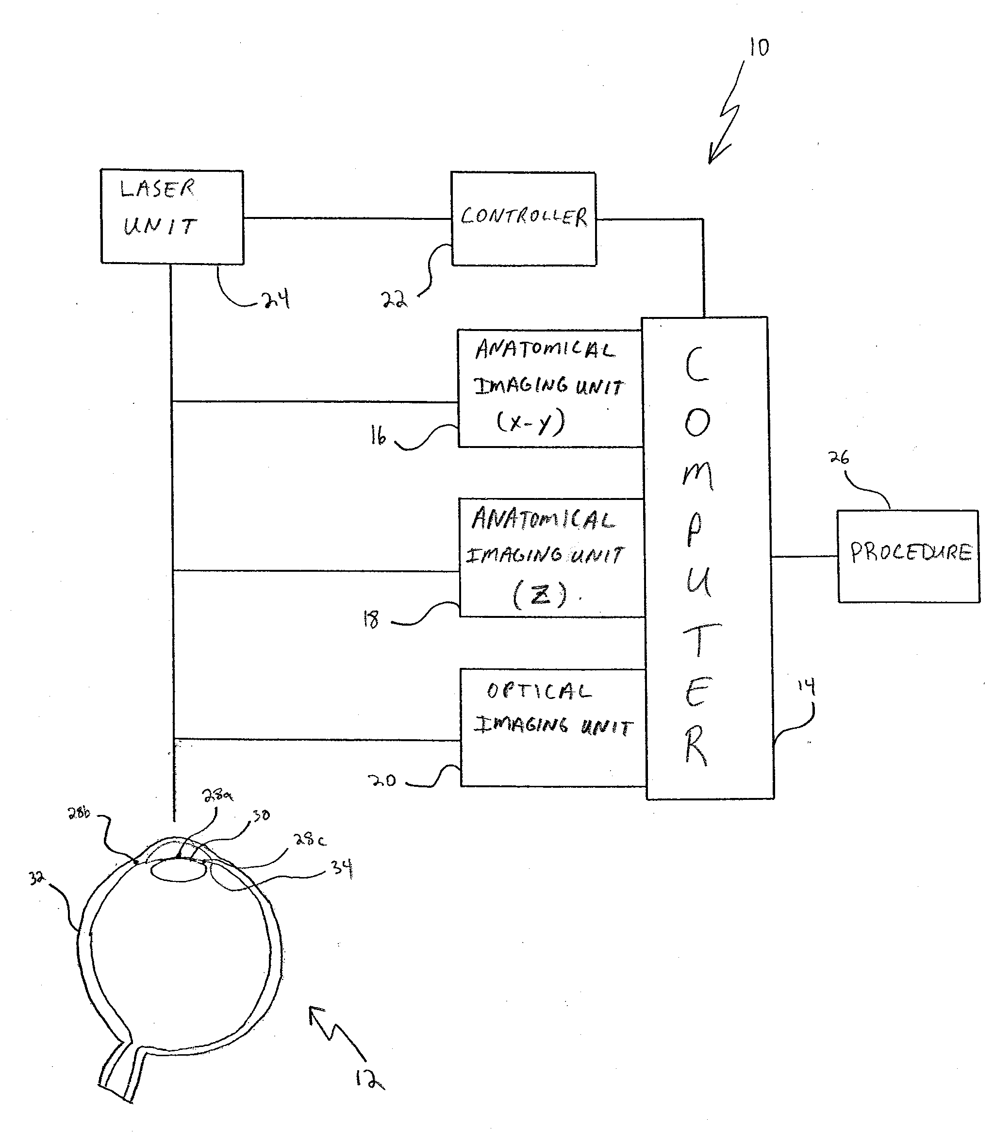
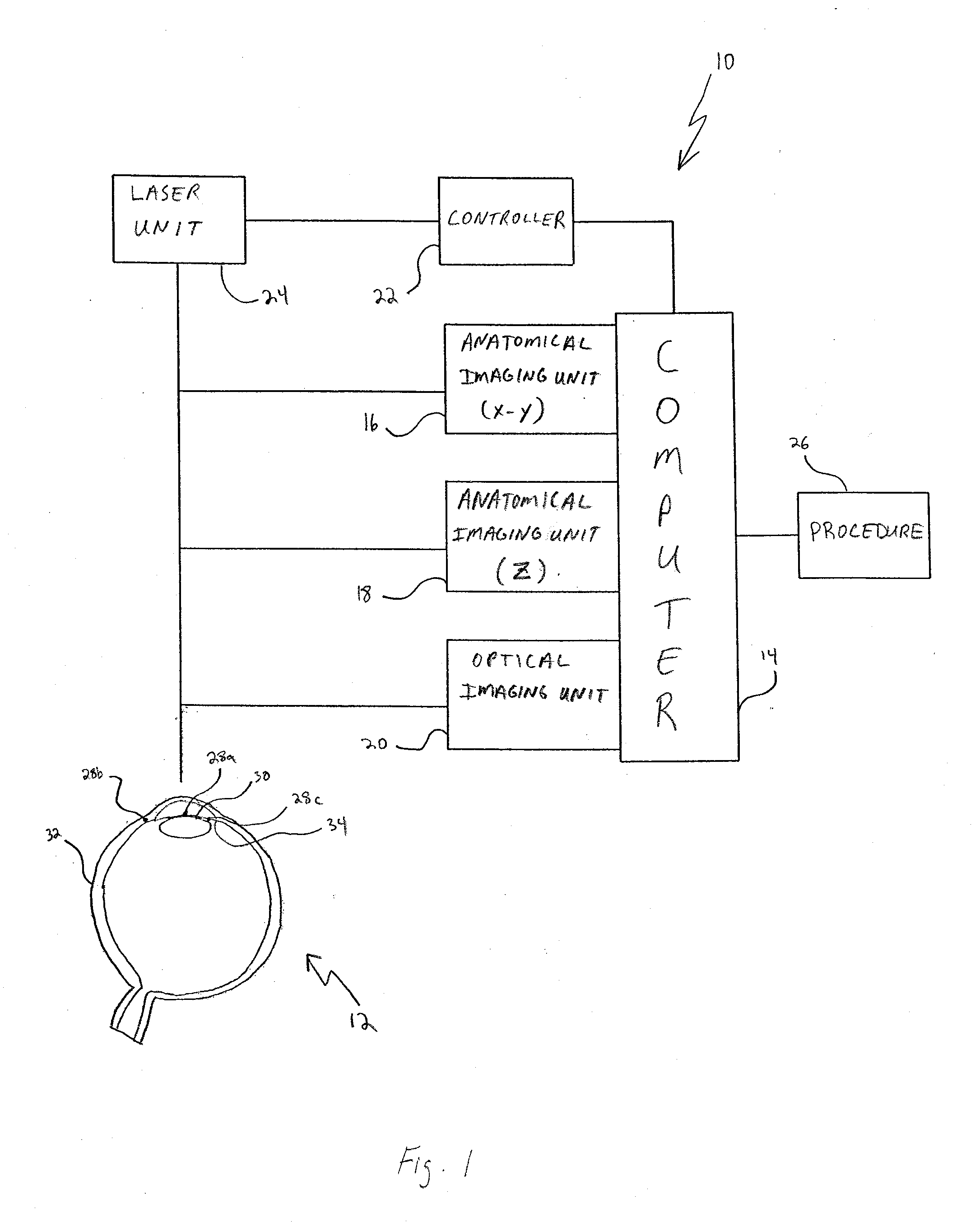
[0014]Referring initially to FIG. 1, the system of the present invention is shown and generally designated 10. As depicted, the system 10 is intended for use with a human eye 12 and includes a computer 14 that is in electronic communication with three detector units 16, 18, and 20. Detector unit 16 is an anatomical detector unit that is used to create a two-dimensional (x-y direction) image of the eye 12. For example, the detector unit 16 may be a camera which can produce either a video image or a still image of the eye 12, or both. Also connected to the computer 14 is the detector unit 18 which is used to supplement the two-dimensional image by adding depth data (z-direction). Like detector unit 16, detector unit 18 is also an anatomical detector unit. For the present invention, several different types of detector units 18 can produce an appropriate image for depth data. Examples of these include the following: an OCT imaging unit, a Scheimpflug imaging unit, a confocal imaging uni...


PUM


Abstract

A system and method are provided for using multiple detectors to create a frame of reference for performing ophthalmic laser surgery. Anatomical detectors generate data sets and a computer program receives these data sets to create the frame of reference. The frame of reference is then used with a selected procedure for conducting ophthalmic laser surgery. An additional detector can measure refractive data of the eye for use as a data set that will refine the frame of reference.

Description

FIELD OF THE INVENTION[0001]The present invention pertains generally to systems and methods for performing ophthalmic surgery. More particularly, the present invention pertains to performing an ophthalmic procedure using multiple detectors to gather data pertaining to the eye prior to and during the surgery. The present invention is particularly, but not exclusively, useful as a system for planning and performing ophthalmic surgery by combining data gathered by anatomical and optical detector units to develop a three-dimensional frame of reference of the eye.BACKGROUND OF THE INVENTION[0002]As is well known, ophthalmic laser surgery can be used to treat a variety of ailments related to the eye. Nearly every part of the eye can benefit from laser-induced changes during ophthalmic surgery to correct various maladies. For instance, ophthalmic laser surgery is commonly used to correct or treat nearsightedness, farsightedness, glaucoma, and cataracts. As would be expected when operating ...

Claims


Application Information

Patent Timeline
Patent Type & Authority Applications(United States)
IPC IPC(8): A61F9/008
CPCA61F9/00825A61F2009/00844A61F2009/00851A61F2009/0088G01N21/4795A61B3/1005A61B3/102A61B3/103A61B3/0058
Inventor LOESEL, FRIEDERTOENNIES, ROLAND
Owner TECHNOLAS PERFECT VISION
Why Eureka
Try Eureka