Mobile object controller and floor surface estimator

a technology of floor surface and estimator, which is applied in the field of mobile object controller and floor surface estimator, can solve the problems of discrepancy with desired moment, inability to accurately determine and inability to adjust the displacement amount of each joint smoothly.

Active Publication Date: 2012-11-29
HONDA MOTOR CO LTD
View PDF9 Cites 39 Cited by
  • Summary
  • Abstract
  • Description
  • Claims
  • Application Information

AI Technical Summary

Benefits of technology

[0177]Therefore, according to the fifth invention, the appropriate value of k (the value of k such that the absolute value of DET is equal to or more than the predetermined threshold) used for calculating the pseudo inverse matrix Jc−1 can be efficiently determined in a short time in each control cycle of the mobile object controller, and also the pseudo inverse matrix Jc−1 can be changed smoothly. This allows the joint displacement correction amount to be determined so as to smoothly change the displacement amo...

Problems solved by technology

In the conventional compliance control technique, however, a change in floor reaction force due to the first correction and a change in floor reaction force due to the second correction tend to interfere with each other.
This is problematic because a change in floor reaction force moment actually generate...

Method used


Image

  • Mobile object controller and floor surface estimator
  • Mobile object controller and floor surface estimator
  • Mobile object controller and floor surface estimator

Examples


first embodiment

[0357]The following describes a first embodiment of the present invention with reference to FIGS. 2 to 5.

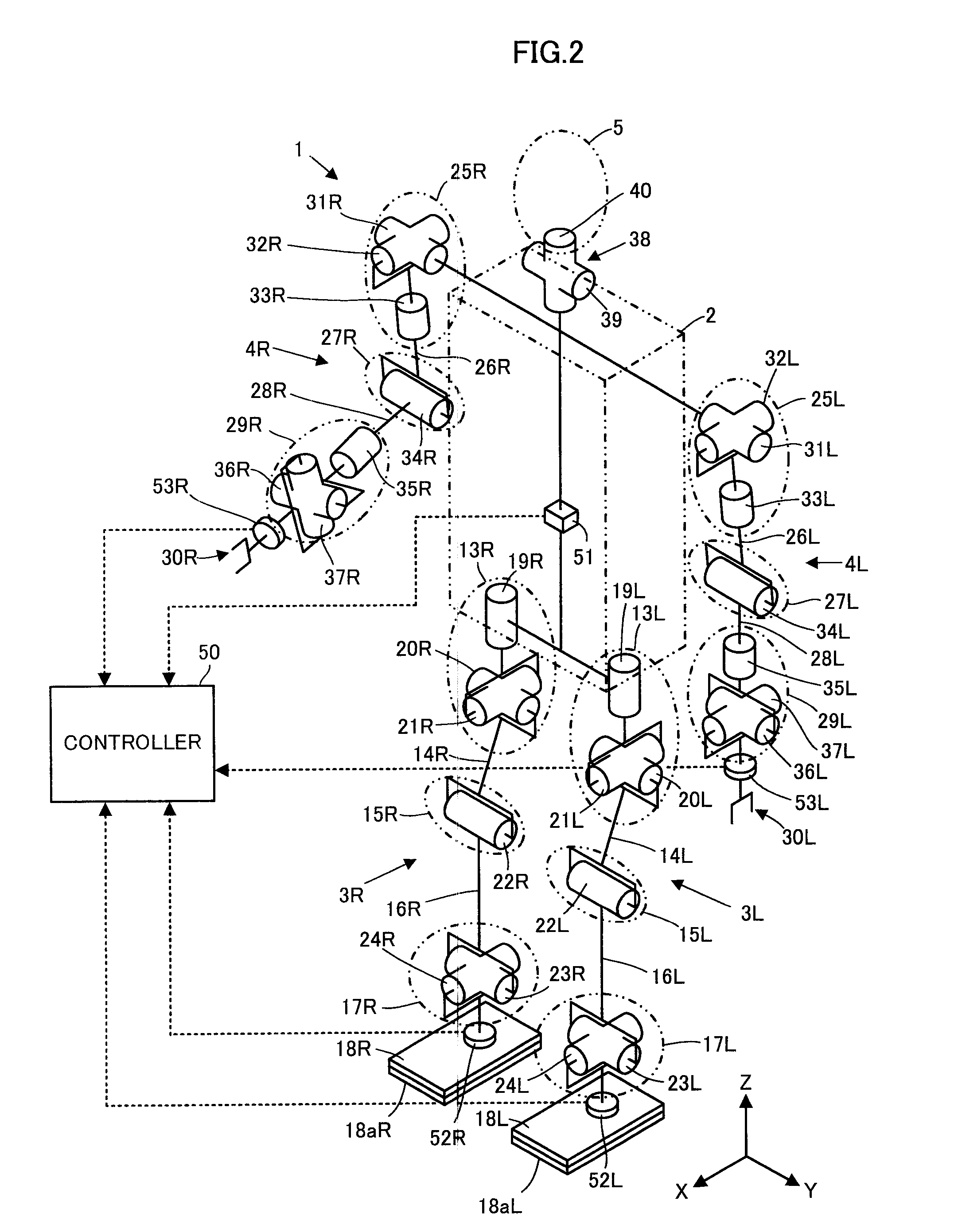
[0358]In FIG. 2, a mobile object 1 exemplified in this embodiment is a legged mobile robot having two leg links as an example. The mobile object 1 includes an upper body 2 as a body, one pair of right and left leg links 3R and 3L, one pair of right and left arm links 4R and 4L, and a head 5.

[0359]In the description of this embodiment, the sign “R” is added to each variable indicating a member or a quantity related to the member on the right side of the mobile object 1 when the mobile object 1 is viewed from the rear, and the sign “L” is added to each variable indicating a member or a quantity related to the member on the left side of the mobile object 1 when the mobile object 1 is viewed from the rear. When it is not particularly necessary to distinguish right from left, however, the signs “R” and “L” may be omitted.

[0360]The pair of right and left leg links 3R and 3L have the sa...

second embodiment

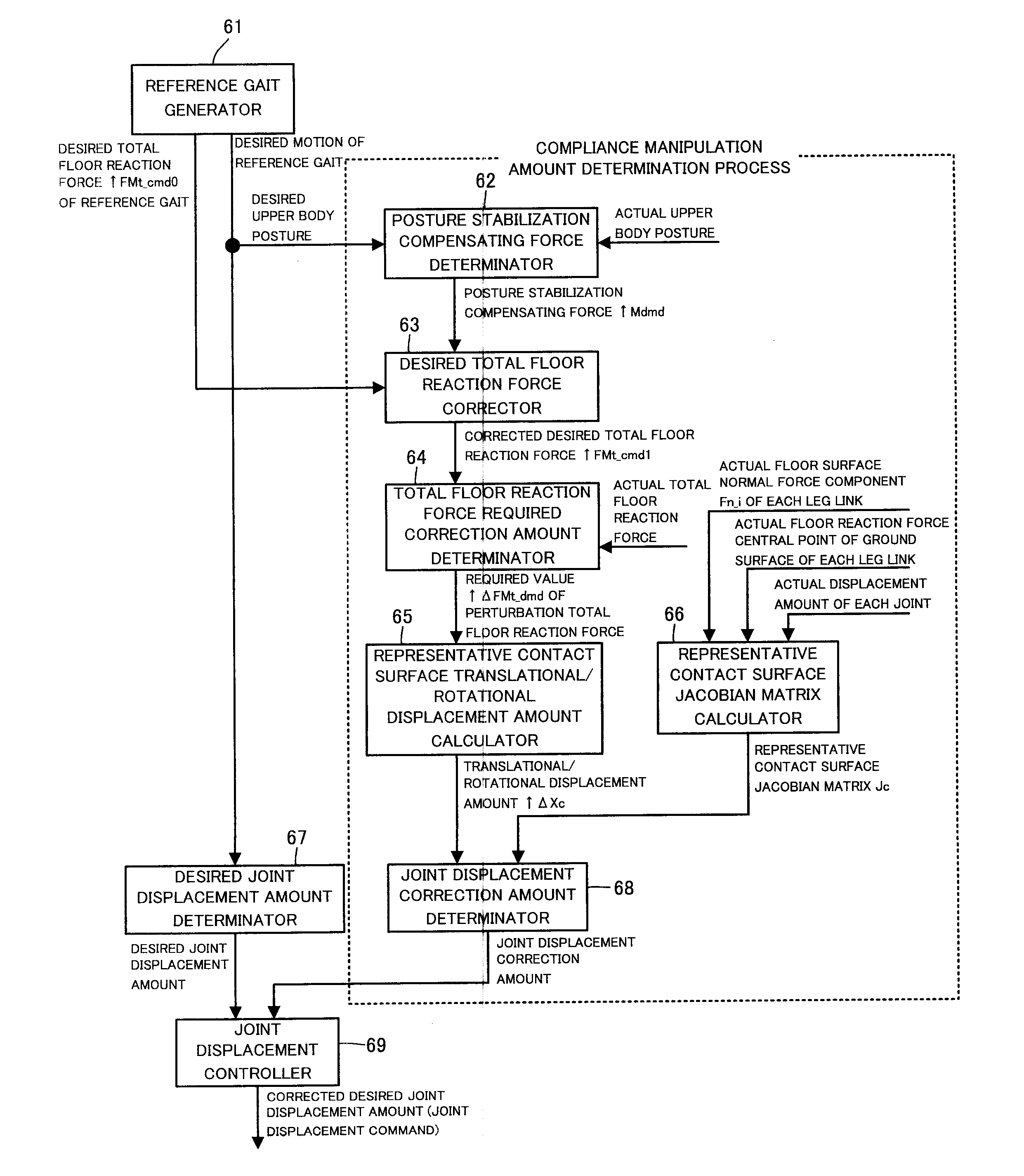
[0507]The following describes a second embodiment of the present invention with reference to FIG. 6. This embodiment differs from the first embodiment only in part of the process of the controller 50. Accordingly, the difference from the first embodiment is mainly described below, while omitting the description of the same matter as the first embodiment.

[0508]In this embodiment, the controller 50 further includes a function of estimating the position and posture of the actual floor surface in the mobile environment of the mobile object 1 using the parameter calculated for the motion control of the mobile object 1, simultaneously with the motion control of the mobile object 1.

[0509]In detail, as shown in FIG. 6, the controller 50 includes a floor surface estimator 70 which estimates the position and posture of the actual floor surface, in addition to the reference gait generator 61, the posture stabilization compensating force determinator 62, the desired total floor reaction force c...

third embodiment

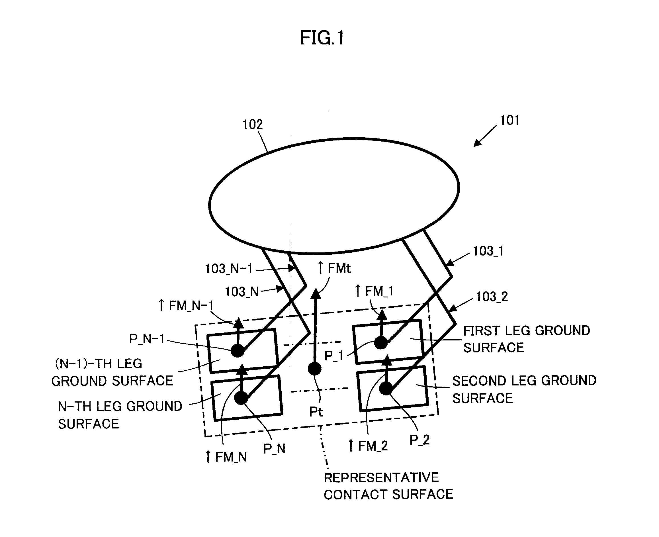
[0542]The following describes a third embodiment of the present invention with reference to FIGS. 10 to 14.

[0543]In FIG. 10, a mobile object 81 exemplified in this embodiment is a mobile robot that includes a body 82 and a plurality of movable links 83a to 83d (hereafter also generically referred to as movable links 83) extending from the body 82. In this embodiment, the number of movable links 83 is four, as an example.

[0544]Each movable link 83 is a link mechanism capable of functioning as a leg or an arm of the mobile object 81. Each movable link 83 includes a plurality of element links 84a to 84c (hereafter also generically referred to as element links 84) and a plurality of joints 85a to 85d (hereafter also generically referred to as joints 85) that connect the element links 84 in sequence from the body 82 side.

[0545]In this embodiment, each of the number of element links 84 and the number of joints 85 constituting each movable link 83 is three, as an example. Of the three elem...


PUM


Abstract

A total floor reaction force required correction amount by which an error between an observed value of a total floor reaction force acting on a mobile object 101 and a desired total floor reaction force approaches zero is converted to a spring displacement amount of a position/posture of a representative contact surface representative of ground surfaces of the mobile object 101. A correction amount of a displacement amount of each joint of the mobile object 101 is determined by multiplying the spring displacement amount by a pseudo inverse matrix of a Jacobian matrix representing a relation between a change amount of the position and posture of the representative contact surface per unit time and a change amount of a generalized variable vector per unit time. The displacement amount of each joint is controlled according to a corrected desired joint displacement amount obtained by correcting a desired joint displacement amount.

Description

BACKGROUND OF THE INVENTION[0001]1. Field of the Invention[0002]The present invention relates to a controller of a mobile object such as a legged mobile robot, and an estimator for estimating a position and posture of a floor surface on which the mobile object moves.[0003]2. Description of the Related Art[0004]In motion control of a mobile object such as a legged mobile robot that moves on a floor surface by moving a plurality of leg links (e.g. repeatedly landing and lifting each leg link) connected to a body, each leg link's joints are basically driven so that an actual motion of the mobile object follows a desired motion of the mobile object.[0005]Typically, the desired motion is generated so as to satisfy kinetic requirements (requirements such as the ZMP existing within a supporting polygon) on a supposed floor surface that is set to represent an actual floor surface. However, a shape error and the like of the supposed floor surface, which is used for generating the desired mot...

Claims


Application Information

Patent Timeline
IPC IPC(8): G05B15/02
CPCB25J9/1664G05B2219/39305G05B2219/39182B62D57/032
Inventor ORITA, ATSUO
Owner HONDA MOTOR CO LTD
Why Eureka
Try Eureka