Brake control system in vehicle

a technology of brake control system and vehicle, which is applied in the direction of braking system, process and machine control, instruments, etc., can solve the problems of vehicle body collapse, abs control cannot be initiated at a proper timing, and vehicle cannot be effectively steered

Active Publication Date: 2012-11-29
KAWASAKI MOTORS LTD
View PDF8 Cites 19 Cited by
  • Summary
  • Abstract
  • Description
  • Claims
  • Application Information

AI Technical Summary

Benefits of technology

[0022]If the value of the decrease rate is farther from the standard decrease rate, i.e., a deviation from the standard decrease rate is greater and the wheel is more likely to be locked, when the rate of the decrease of the wheel speed which is attributed to the braking force exceeds the standard decrease rate during braking, the threshold is changed into a smaller value. This allows the determination as to the initiation of the ABS control to be performed ea

Problems solved by technology

When the wheel is locked, the vehicle becomes undirected, so that the vehicle cannot be steered effectively, or a vehicle body collapses.
In some cases, the ABS control cannot be initiated at a proper timing, due to low calculation accuracy of the slip ratio.
However, the above stated prior art example is effective in a particular situation in w

Method used


Image

  • Brake control system in vehicle
  • Brake control system in vehicle
  • Brake control system in vehicle

Examples


embodiment 1

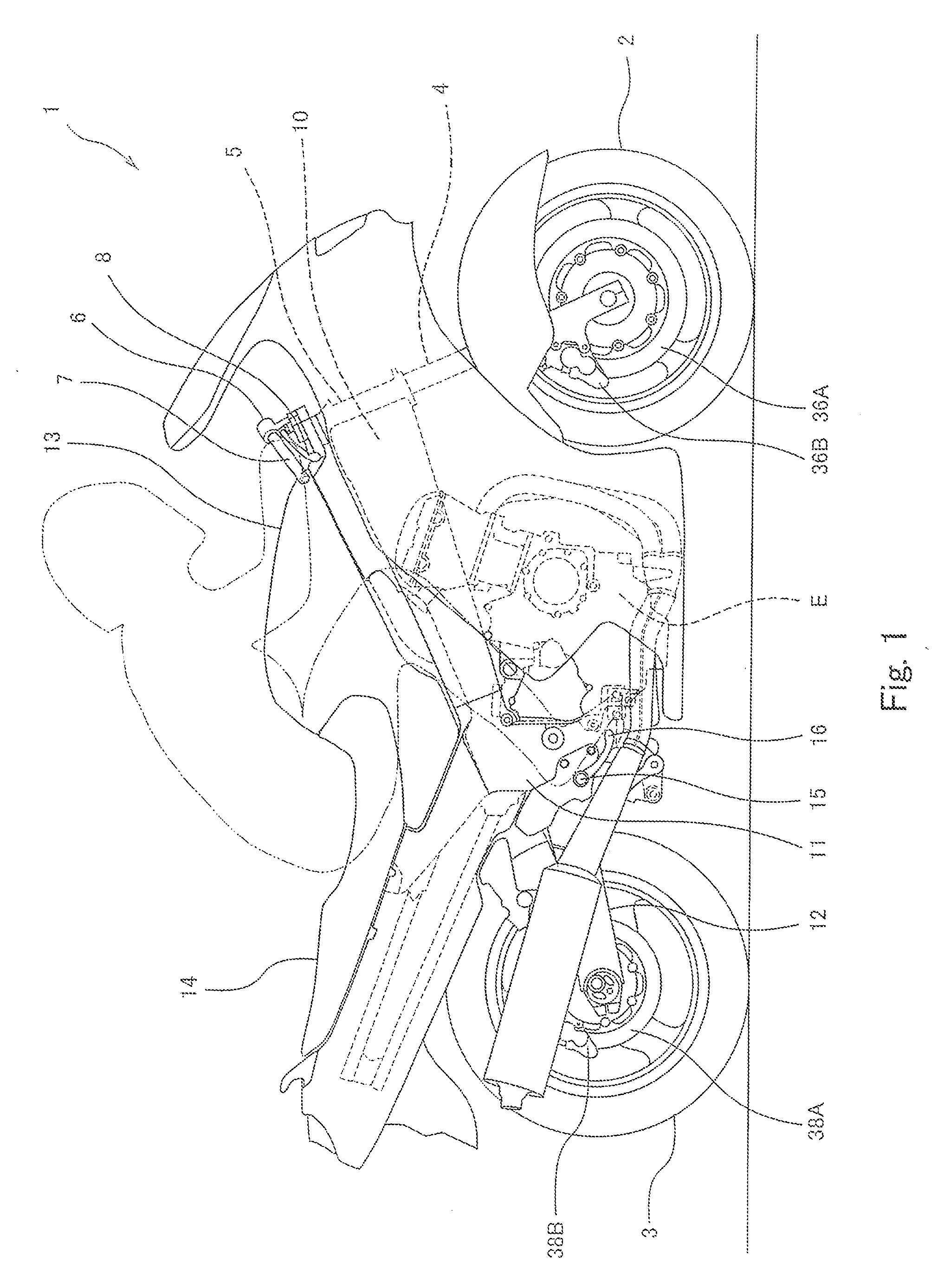
[0042]FIG. 1 is a right side view of a motorcycle 1 according to the embodiment of the present invention. As shown in FIG. 1, the motorcycle 1 includes a front wheel 2 which is a driven wheel and a rear wheel 3 which is a drive wheel. The front wheel 2 is rotatably mounted to a lower end portion of a front fork 4 extending substantially vertically. The front fork 4 is mounted to a steering shaft (not shown) via a pair of upper and lower brackets (not shown). The steering shaft is rotatably supported by a head pipe 5 provided on a vehicle body.

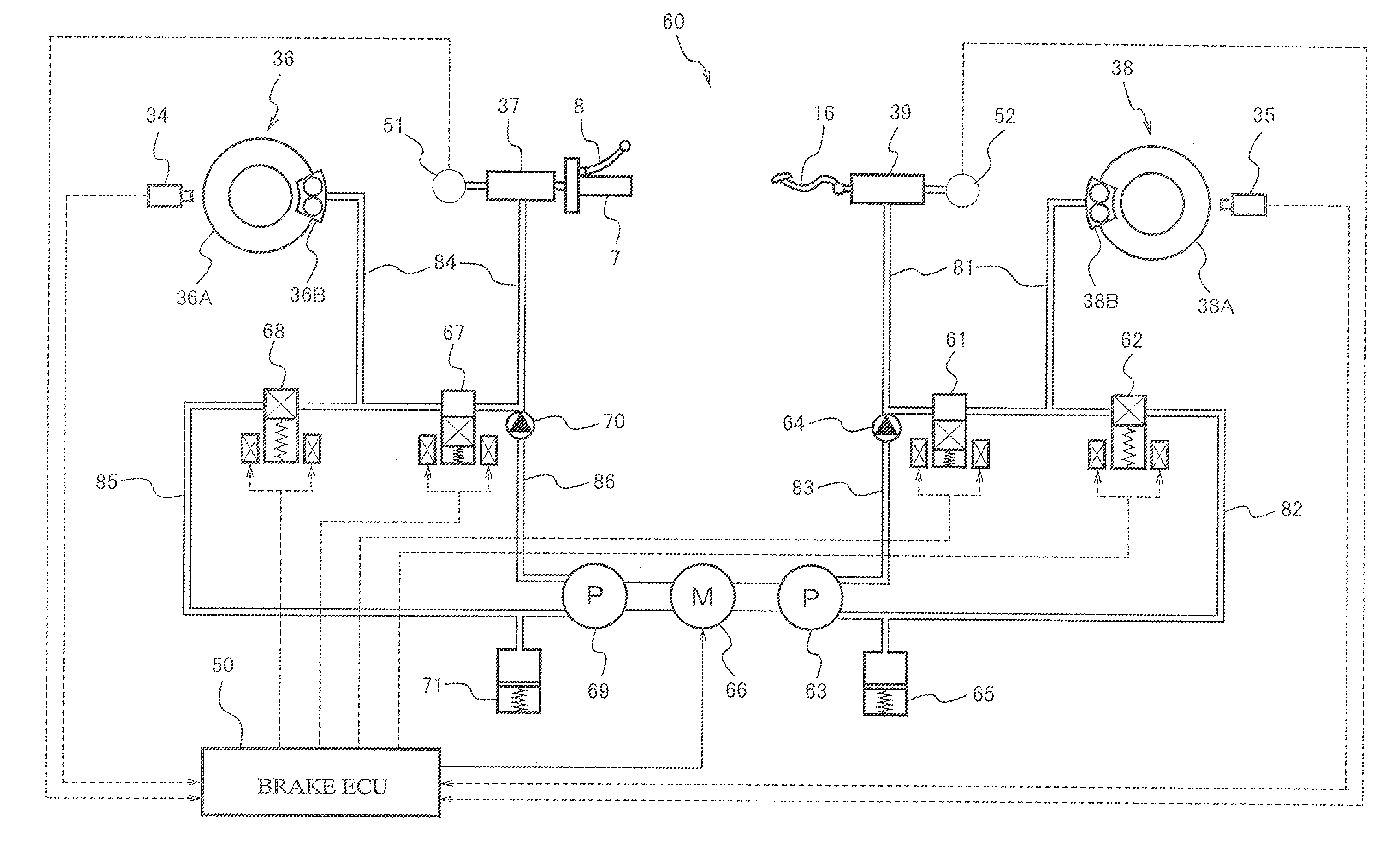
[0043]A bar-type steering handle 6 extending in a rightward and leftward direction is attached to the upper bracket coupled to an upper end of the front fork 4. The driver steers the steering handle 6 to steer the front fork 4 and the front wheel 2. A front wheel brake caliper 36B is mounted to a lower end portion of the front fork 4 such that the brake caliper 36B seizes a front wheel brake disc 36A rotatable together with the front wheel 2. T...

embodiment 2

[0107]Hereinafter, Embodiment 2 of the present invention will be described. In Embodiment 2, the threshold ΔVf*, ΔVr* used to determine whether or not to initiate the ABS control in the first determiner section 54 is changed, based on the driving state of the motorcycle 1. The other constituents are identical to those of Embodiment 1. Therefore, they are identified by the same reference symbols and will not be described.

[0108]In the present embodiment, the driving state detector section 53 in the brake ECU 50 changes the threshold ΔVf*, ΔVr* based on a magnitude of the brake pressure P or change in the brake pressure P. For example, based on the change in the brake pressure P, the driving state detector section 53 detects that the driver has performed a quick brake operation. According to this, the driving state detector section 53 changes the threshold ΔVf*, ΔVr* to enable the ABS control to be initiated more easily.

[0109]To this end, a new step is provided between step S7 and step...

embodiment 3

[0118]Hereinafter, Embodiment 3 of the present invention will be described. In Embodiment 3, the threshold ΔVf*, ΔVr* used to determine whether or not to initiate the ABS control is changed based on the wheel speed decrease rate ΔVf, ΔVr calculated in the first determiner section 54 during braking. The other constituents are identical to those of Embodiment 1. Therefore, they are identified by the same reference symbols and will not be described.

[0119]In the present embodiment, as indicated by a downward arrow L3 of FIG. 10A, when the decrease rate ΔVr of the rear wheel speed Vr increases and exceeds a standard decrease rate on the braking characteristic line B, i.e., becomes below the braking characteristic line B, as a result of the brake operation, the threshold ΔVf* may be changed such that the threshold ΔVf* is smaller as a value of a difference α between the standard decrease rate corresponding to the brake pressure P at that point of time and the decrease rate ΔVr (actual dec...


PUM


Abstract

A brake control system in a vehicle which executes anti-lock brake control for controlling a braking force applied to a wheel to prevent the wheel from being locked during braking of the vehicle is provided. The brake control system includes an initiation determiner section for determining whether or not an initiation condition used to initiate the anti-lock brake control is met the initiation condition including a condition in which a decrease rate of a wheel speed which is a rotational speed of the wheel is not less than a predetermined threshold; and a brake control section for initiating control of the braking force applied to the wheel in the anti-lock brake control, if the initiation determiner section determines that the initiation condition is met.

Description

BACKGROUND OF THE INVENTION[0001]1. Field of the Invention[0002]The present invention generally relates to a brake control system which controls a braking force applied to a wheel to prevent the wheel from being locked during braking of the vehicle. More particularly, the present invention relates to a technique for initiating brake control at a proper timing.[0003]2. Description of the Related Art[0004]During braking of a vehicle, a gripping force of a tire with respect to a road surface is lessened due to a braking force applied to the vehicle, and rotation of the wheel almost stops. This is called a brake lock or a lock. When the wheel is locked, the vehicle becomes undirected, so that the vehicle cannot be steered effectively, or a vehicle body collapses.[0005]To prevent the wheel from being locked, anti-lock brake control (hereinafter referred to as ABS control) is known, which controls a braking force applied to the wheel. This ABS control is as follows. If a slip ratio of the...

Claims


Application Information

Patent Timeline
IPC IPC(8): B60T8/176
CPCB60T8/1706
Inventor MATSUDA, YOSHIMOTO
Owner KAWASAKI MOTORS LTD
Why Eureka
Try Eureka