

Integrated vehicle part delivery and build system
- Summary
- Abstract
- Description
- Claims
- Application Information
AI Technical Summary
Benefits of technology
Problems solved by technology
Method used
Image

Examples
Embodiment Construction
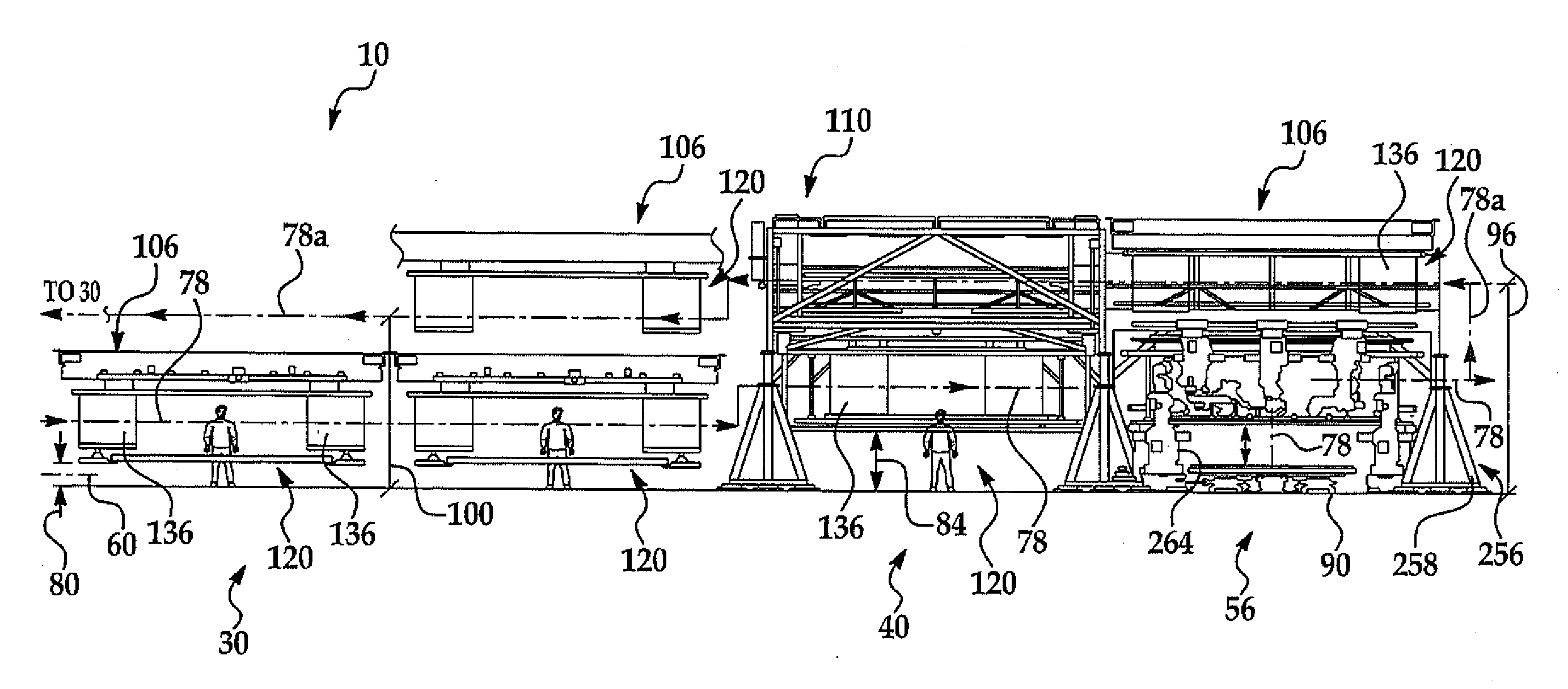
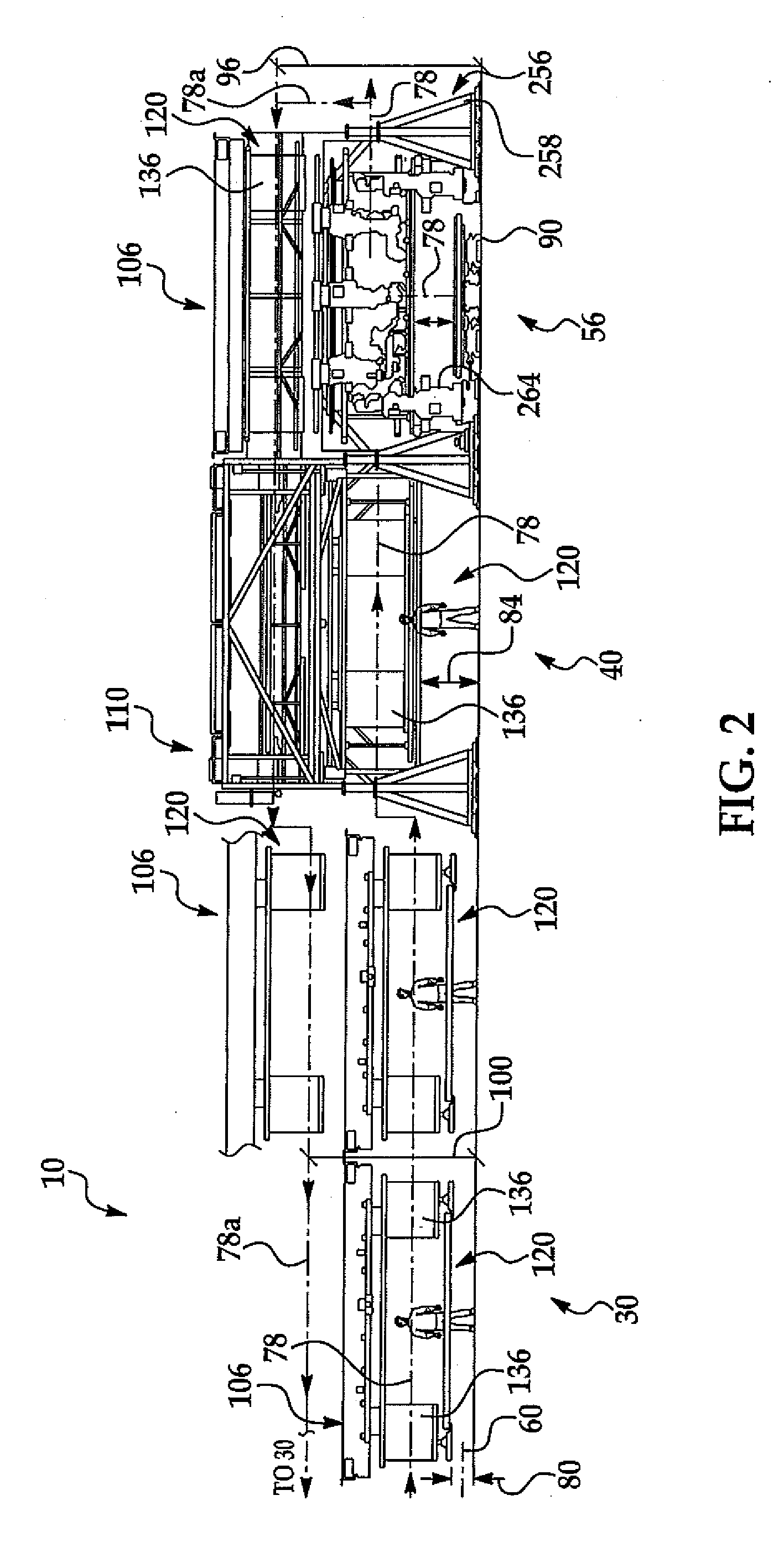
[0025]Referring to FIGS. 1-12 an integrated vehicle part delivery and build apparatus and method for sequenced, vehicle-specific part delivery and assembly is illustrated and examples explained below.
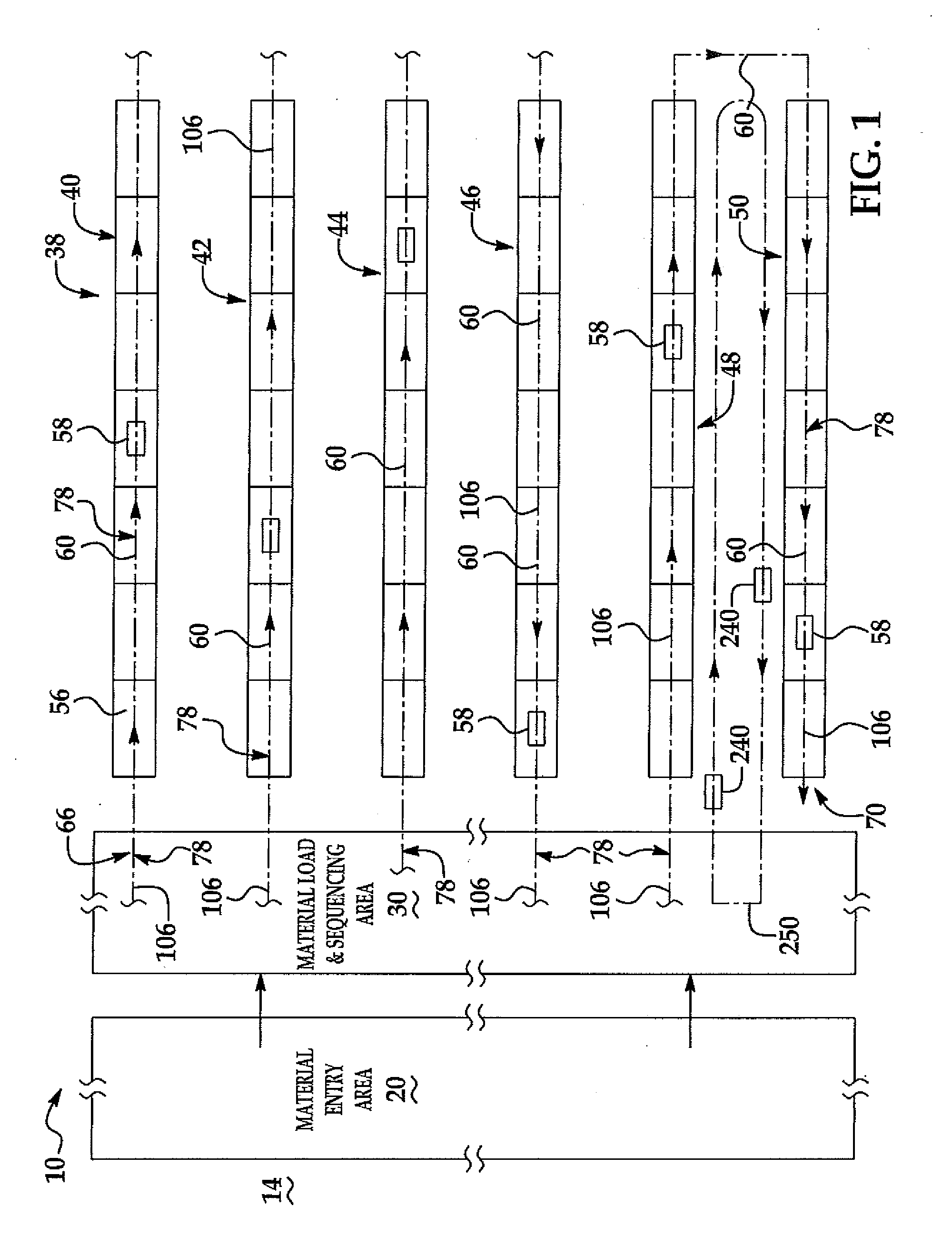
[0026]Referring to FIG. 1, an example of a integrated vehicle part delivery and build system 10 useful on an example of assembly plant floor 14 for body-in-white (BIW) vehicle body structures 58 is shown. In the example, the system 10 includes a material entry area 20, a material loading and sequencing or staging area 30, and a plurality of main assembly lines 38 (six shown in FIG. 1 and identified as 40-50 as illustrated). Each assembly line 38 includes a vehicle travel path 60 running down each line 40-50.
[0027]Referring to the example in FIG. 1, simplified for purposes of illustration, there is an assembly line starting position 66 and an ending position 70 with vehicle body build path 60. In the example shown, each individual assembly line 40, 42, 44 and 46 have an independent vehic...
PUM
| Property | Measurement | Unit |
|---|---|---|
| Fraction | aaaaa | aaaaa |
| Area | aaaaa | aaaaa |
Abstract
Description
Claims
Application Information