

Pump unit and breathing assistance device
- Summary
- Abstract
- Description
- Claims
- Application Information
AI Technical Summary
Benefits of technology
Problems solved by technology
Method used
Image


Examples
first embodiment
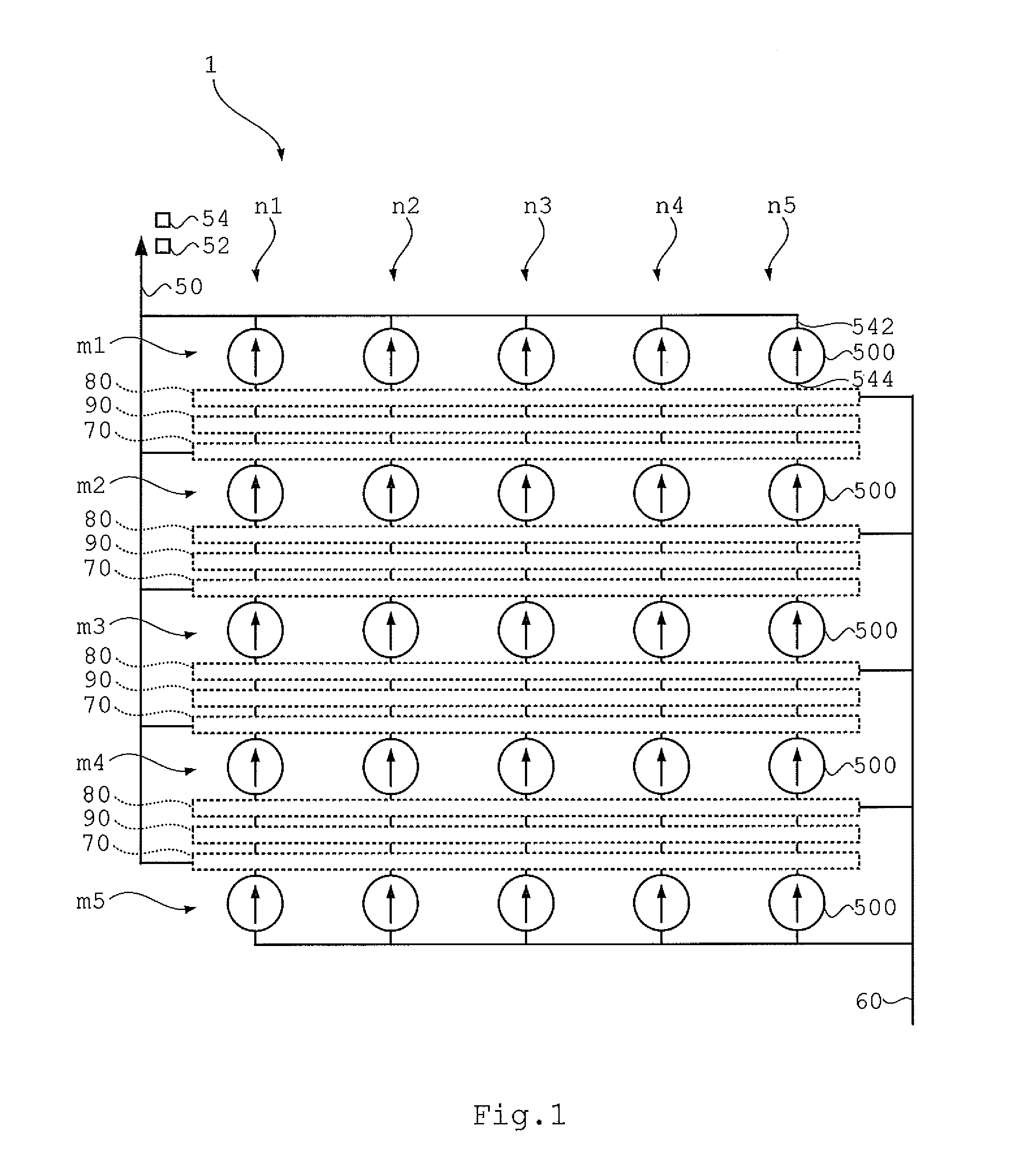
[0039]FIG. 1 shows an example of the conceptual structure of a pump unit 1 according to the present invention. The pump unit 1 includes a plurality of (here, 25) micropumps 500 arranged in a lattice pattern when viewed conceptually with m1-th to m5-th rows and n1-th to n5-th columns. The micropumps 500 transfer a fluid in a direction along the n1-th to n5-th columns.
[0040]An example of the structure of the micropump 500 is described first by referring to FIG. 2A. The micropump 500 is suggested in patent literature WO 2008 / 069266. In the micropump 500, a piezoelectric element 501 is fixed to a diaphragm 502, and a vibrating wall 520 is arranged to face the diaphragm 502, thereby forming a first blower chamber 520A. The vibrating wall 520 is provided with an opening 522 through which a fluid moves into and out of the first blower chamber 520A. Further, a second blower chamber 540 communicating with the opening 522 is formed outside the first blower chamber 520A. The second blower cham...
second embodiment
[0061]In the pump unit 1 of the second embodiment, the discharge-side confluence space 72, the intake-side branching space 82, and the switching valve 65 provided for each parallel pump unit 600 switch the connections of all micropumps 500 belonging to each parallel pump unit 600 at a time.
[0062]FIGS. 9A and 9B show examples of control of the pump unit 1 of the second embodiment that is also made by the controller 10 of FIG. 1.
[0063]In FIG. 9A, all the series-connection valves 92 are in a shutoff state (OFF), and all the discharge direct-connection valves 74 and the intake direct-connection valves 84 are in a state of forming direction connection (ON). Accordingly, all the upstream parallel pump units 600 and downstream parallel pump units 600 are connected in parallel. Accordingly, the discharge ports 542 of all the micropumps 500 are directly connected to the integrated discharge port 50, and the intake ports 544 of all the micropumps 500 are directly connected to the integrated i...
PUM
 Abstract
Description
Claims
Application Information