In-line-type fluid mixer

a fluid mixer and mixer technology, applied in the field of fluid mixers, can solve the problems of increasing the cost of producing the apparatus, damage to the inner wall, etc., and achieve the effects of increasing the speed of raw water injection, reducing the sectional area, and enhancing the mixing

Inactive Publication Date: 2012-12-06
ASAHI YUKIZAI KOGYO CO LTD
View PDF7 Cites 275 Cited by
  • Summary
  • Abstract
  • Description
  • Claims
  • Application Information

AI Technical Summary

Benefits of technology

[0006]It is, on the other hand, possible to enhance the mixing effect by further decreasing the sectional area of the jet 112 of the nozzle member 111 and increasing the velocity of raw water injection. However, as the velocity of flow of the raw water reaches a predetermined value, cavitation may occur, causing damages to the inner wall of the pipe in the downstream of the ejector 109.
[0007]The object of the present invention is to provide an in-line-type fluid mixer which is capable of homogeneously mixing a plurality of fluids together and of preventing the inner wall of the pipe from being damaged even in the conditions where the cavitation may occur.

Problems solved by technology

Accordingly, the raw water and the chemical solution cannot be sufficiently homogeneously mixed together, causing inhomogeneity.
This complicates the apparatus as a whole, resulting in an increased cost for producing the apparatus.
However, as the velocity of flow of the raw water reaches a predetermined value, cavitation may occur, causing damages to the inner wall of the pipe in the downstream of the ejector 109.

Method used


Image

  • In-line-type fluid mixer
  • In-line-type fluid mixer
  • In-line-type fluid mixer

Examples


first embodiment

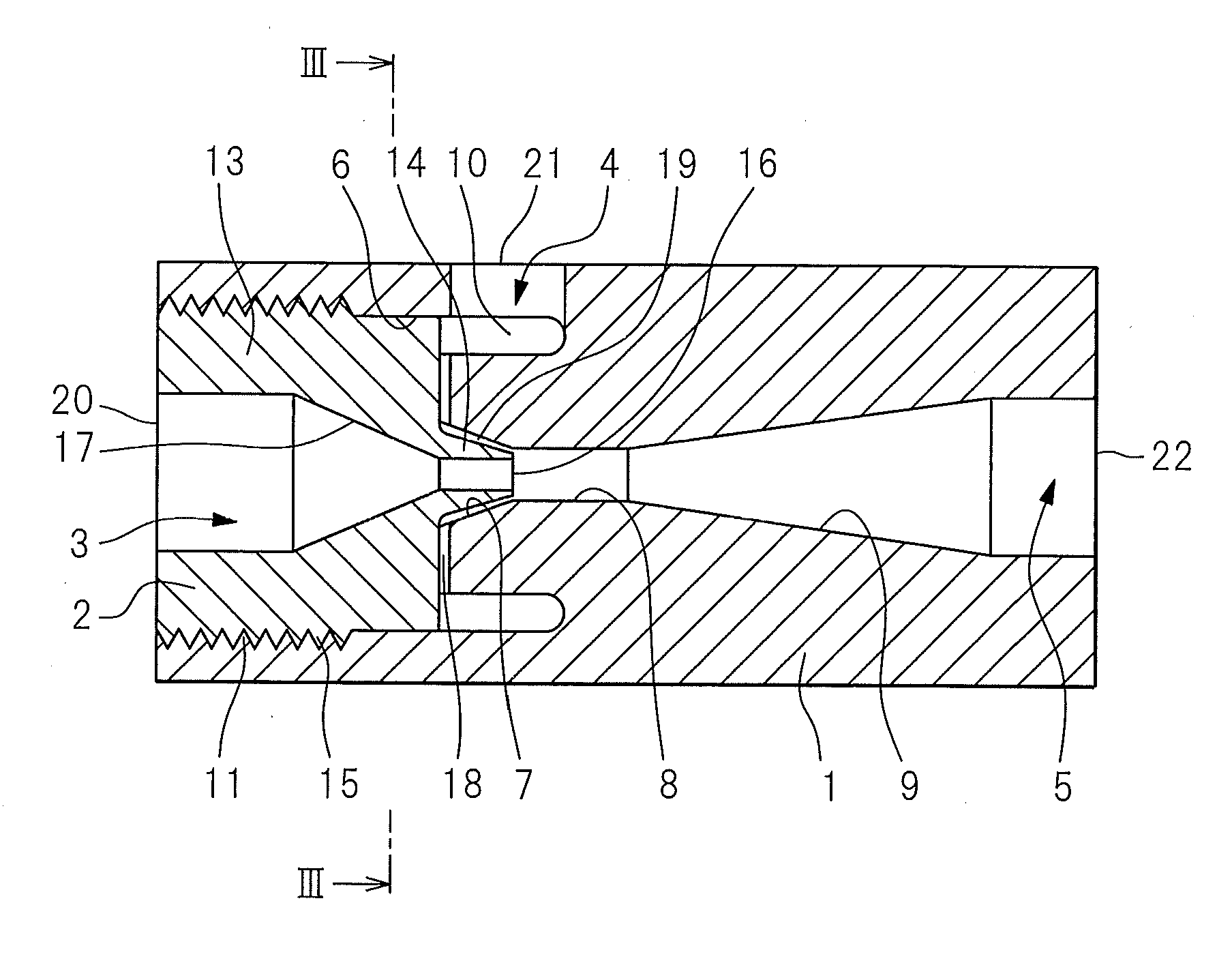
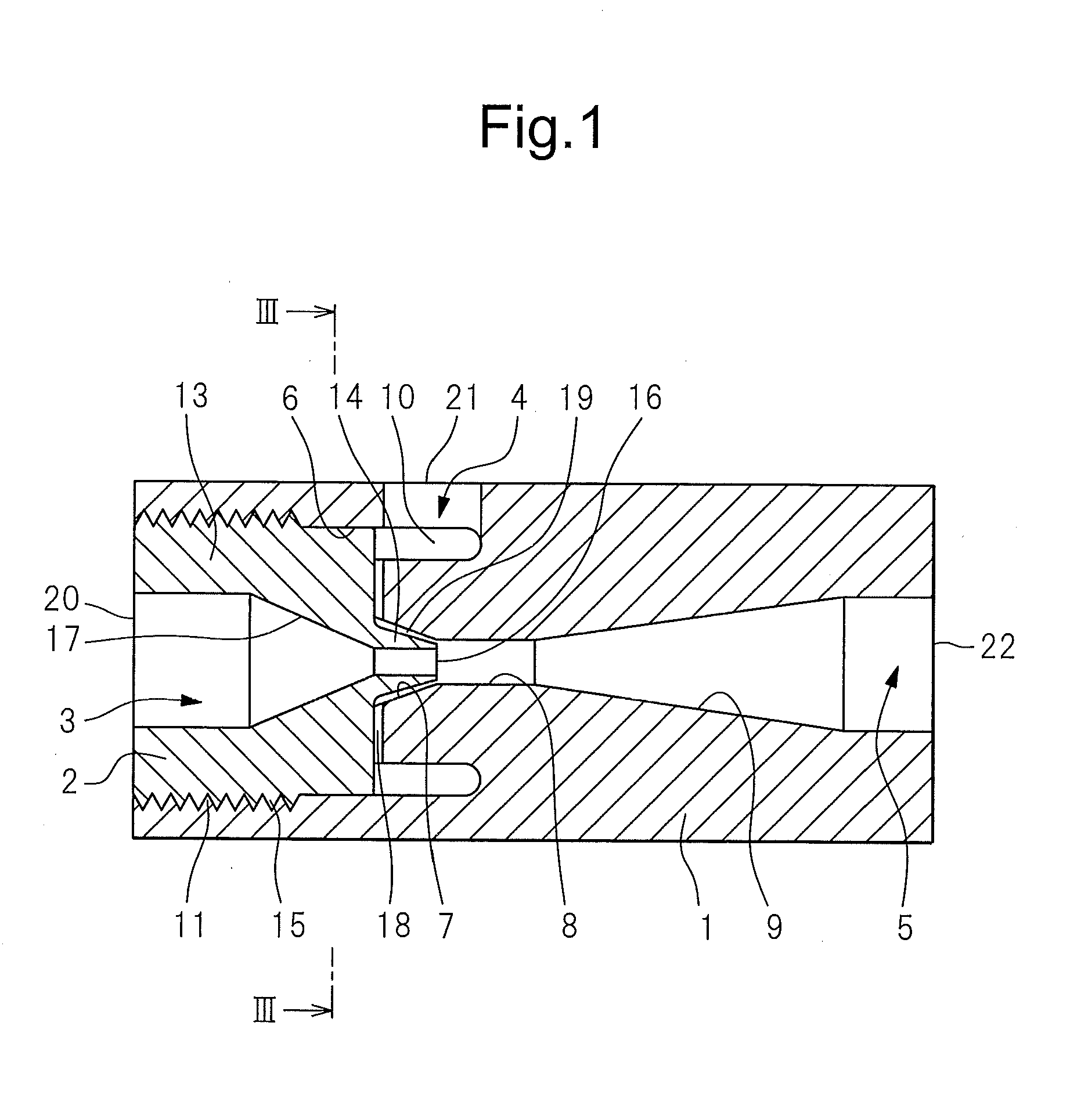
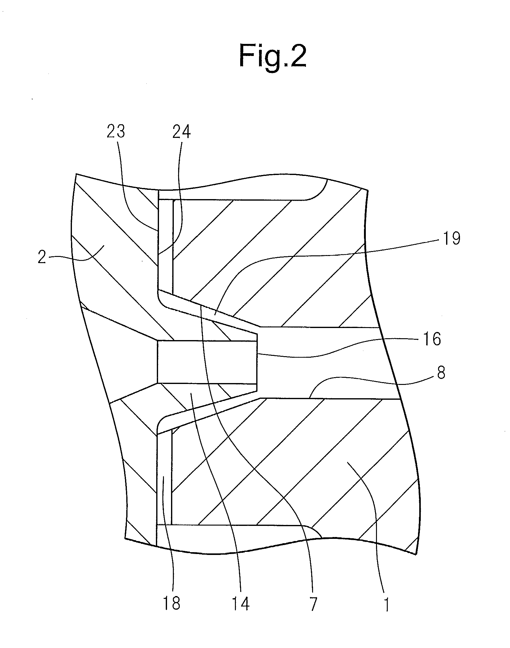
[0024]An in-line-type fluid mixer according to a first embodiment of the invention will be described below with reference to FIGS. 1 to 6. FIG. 1 is a lengthwise sectional view showing the constitution of the in-line-type fluid mixer according to the first embodiment of the invention, and FIG. 2 is an enlarged view of a major portion of FIG. 1. The fluid mixer includes a main body 1 having a substantially cylindrical outer shape, and a nozzle member 2 having a substantially cylindrical outer shape and being fitted to the main body 1.

[0025]The main body 1 is provided, in its one end surface, with a receiving portion 6 into which the nozzle member 2 is fitted and is provided, in its other end surface, with an outlet port 22 that forms an outlet channel 5. The receiving portion 6 has an internally threaded portion 11 formed in the inner circumferential surface thereof at the side of the port. The receiving portion 6 has an circular ring groove portion 10 formed on the bottom surface 23...

example 1

[0040]In Example 1, an apparatus was configured such that the groove portions 12 of the main body 1 were formed in a radially curved manner as shown in FIG. 3, so as to generate a whirling stream. By using this apparatus, the flow rate of the primary fluid (water) introduced into the second inlet channel 4 and the flow rate of the secondary fluid (water) sucked from the first inlet channel 3 were measured, respectively, when the flow rate of the primary fluid flowing through the apparatus varies.

second embodiment

[0049]A second embodiment of the invention will be described with reference to FIGS. 7 and 8. The second embodiment is different from the first embodiment in regard to the configuration of the communication channel 18. Specifically, in the first embodiment, the communication channel 18 is formed by the groove portions 12 on the bottom surface 23 of the receiving portion 6 of the main body 1. In the second embodiment, on the other hand, groove portions are formed on the end surface 24 of the nozzle member 2 at the side of the protruding portion 14. FIG. 7 is a view showing the configuration of a major portion of the in-line-type fluid mixer according to the second embodiment, and is a front view of the nozzle member 2 taken from the side of the outlet port 22 in FIG. 1. The same elements as those in FIGS. 1 and 2 are denoted by the same reference numerals, and the following description will be mainly directed to differences from the first embodiment.

[0050]Referring to FIG. 7, a plura...


PUM

PropertyMeasurementUnit
inner diameteraaaaaaaaaa
sectional areaaaaaaaaaaa

Abstract

An in-line-type fluid mixer is provided, which includes a first channel-forming part defining a first inlet channel from a first inlet portion to a first passage portion; a second channel-forming part defining a second inlet channel from a second inlet portion to a second passage portion; a third channel-forming part defining an outlet channel having a sectional area that increases from a narrower portion through a flaring portion to an outlet portion, and being communicated with the first inlet channel and the second inlet channel, respectively, at an end of the narrow portion; and a whirling stream-generating part for generating a whirling stream in at least one of the first inlet channel and the second inlet channel.

Description

TECHNICAL FIELD[0001]This invention relates to a fluid mixer used for fluid transport piping in a variety of industries such as chemical plants or in the field of semiconductor production, in the field of foods, in the field of medicine, in the field of biotechnology, etc. Specifically, the invention relates to an in-line-type fluid mixer capable of mixing and homogeneously stirring a plurality of fluids in a pipeline.BACKGROUND ART[0002]In order to mix a plurality of fluids together in-line, there has heretofore been employed a method by making use of a Venturi tube which, as shown in FIG. 13, has a narrowing channel forming a contracting portion 104, a throat portion 105 and a flaring portion 106 in a continuing manner. In FIG. 13, a primary fluid flows in through an inlet channel 101, passes through the contracting portion 104, throat portion 105 and flaring portion 106 in this order, and flows into an outlet channel 103. In this case, the throat portion 105 is designed to have a...

Claims


Application Information

Patent Timeline
Patent Type & Authority Applications(United States)
IPC IPC(8): B01F5/06
CPCB01F3/0865B01F5/0413B01F5/043B01F2215/0036B01F2005/0441B01F2215/0034B01F2005/0017Y10T137/87587B01F23/451B01F2025/913B01F25/312522B01F25/31243B01F25/312B01F2101/2202B01F2101/2204B01F25/30B01F35/71
Inventor HANADA, TOSHIHIROLI, SHENGLI
Owner ASAHI YUKIZAI KOGYO CO LTD
Why Eureka
Try Eureka