
Method and system for evaluating an object

Active Publication Date: 2012-12-06
APPL MATERIALS ISRAEL LTD
View PDF0 Cites 1 Cited by
  • Summary
  • Abstract
  • Description
  • Claims
  • Application Information

AI Technical Summary

Problems solved by technology

This hybrid comparison process suffers from the mentioned above drawbacks of die to die comparison and from the drawbacks of cell to cell comparison.

Method used


Image

  • Method and system for evaluating an object
  • Method and system for evaluating an object
  • Method and system for evaluating an object

Examples


Embodiment Construction

[0025]A method, system and computer program product for evaluating an object such as a wafer, a mask or reticles for micro-fabrication, flat panel displays, micro-electromechanical (MEMs) devices and the like during or after manufacture.

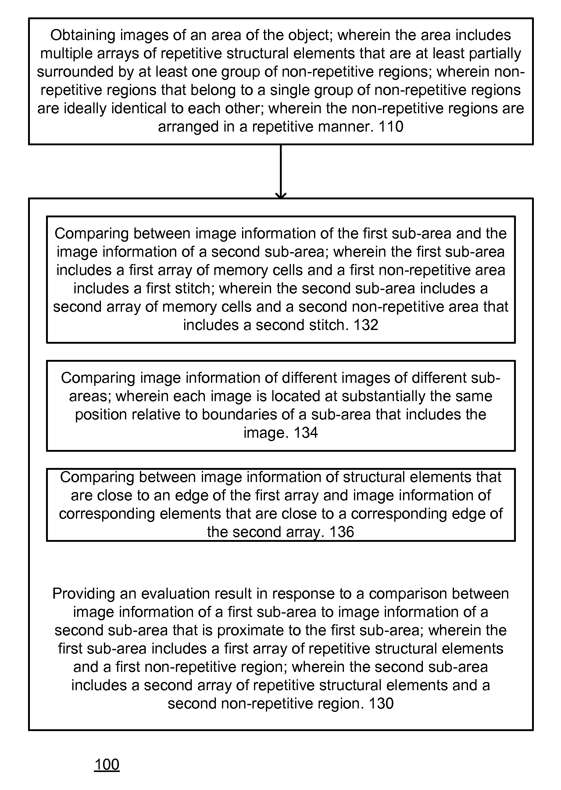
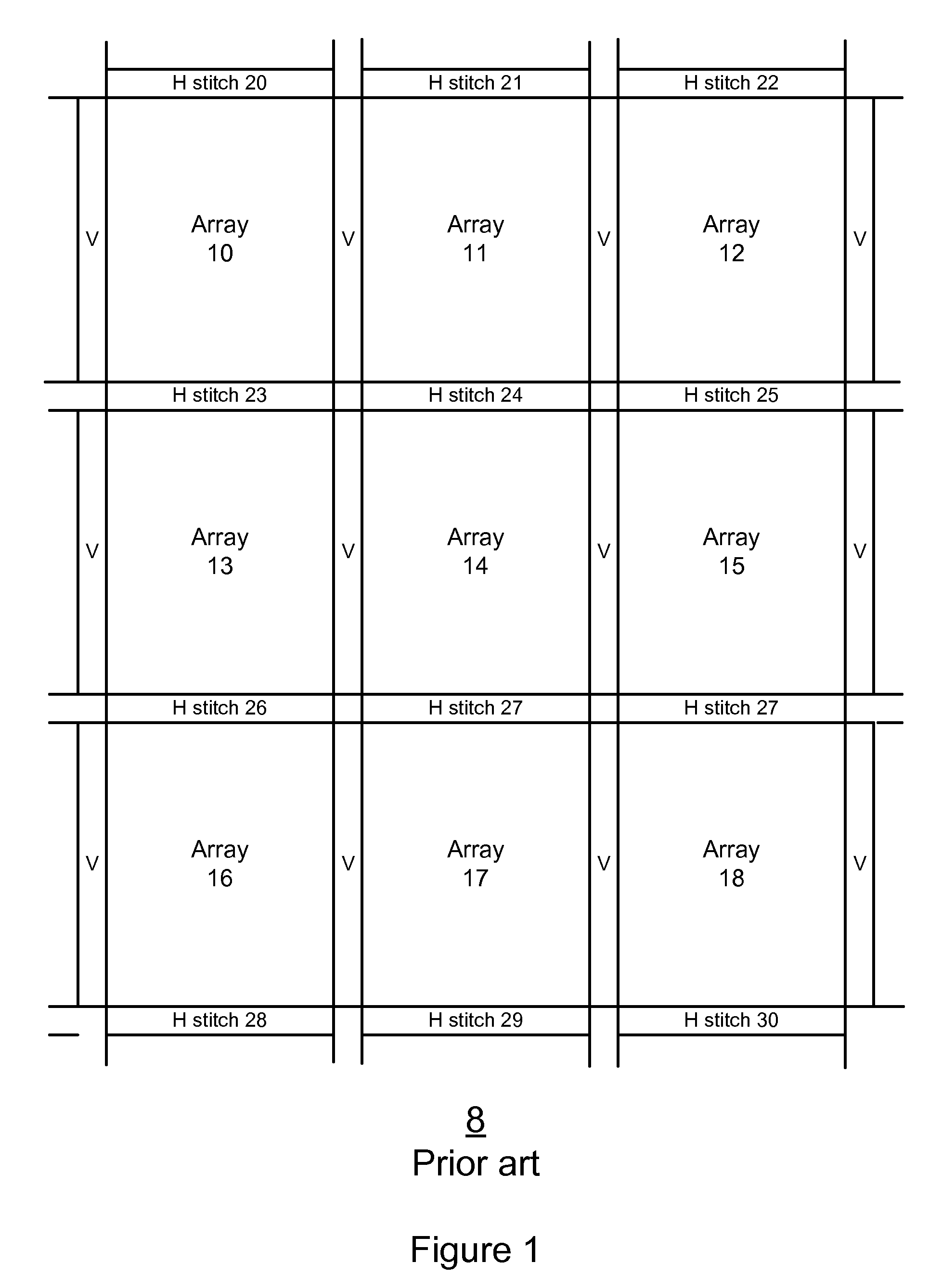
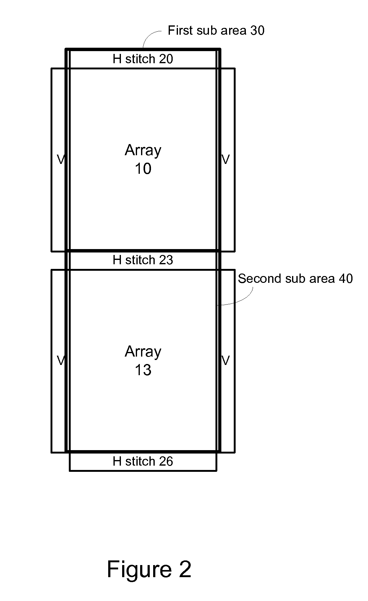
[0026]According to an embodiment of the invention sub-areas are defined. Each subarea includes an array of repetitive structural elements. The array of repetitive structural elements is surrounded by at least one group of non-repetitive regions. Non-repetitive regions that belong to a single group of non-repetitive regions are ideally identical to each other. The non-repetitive regions are arranged in a repetitive manner. Instead of did to die comparison the method, system and computer program product apply another comparison. This comparison is made between image information of non-repetitive regions that belong to sub-areas (usually of the same die) that are proximate to each other. This type of comparison is more robust as it is less affected by p...


PUM


Abstract

A method, system and a computer program product for evaluating a object; the method includes: (i) obtaining an image of an area of the object; wherein the area comprises multiple arrays of repetitive structural elements that are at least partially surrounded by at least one group of non-repetitive regions; wherein non-repetitive regions that belong to a single group of non-repetitive regions are ideally identical to each other; wherein the non-repetitive regions are arranged in a repetitive manner; and(ii) providing an evaluation result in response to a comparison between image information of a first sub-area to image information of a second sub-area that is proximate to the first sub-area; wherein the first sub-area comprises a first array of repetitive structural elements and a first non-repetitive region; wherein the second subarea comprises a second array of repetitive structural elements and a second non-repetitive region.

Description

RELATED APPLICATIONS[0001]This application is a CONTINUATION of, claims priority to and incorporates by reference U.S. application Ser. No. 12 / 100,334 filed Apr. 9, 2008.FIELD OF THE INVENTION[0002]This invention is generally in the field of automatic inspection of objects such as wafers, masks or reticles for micro-fabrication, flat panel displays, micro-electromechanical (MEMs) devices and the like.BACKGROUND OF THE INVENTION[0003]Over the past decade, defect inspection to detect microscopic manufacturing defects has become a standard part of micro-fabrication manufacturing flows, especially for semiconductor wafers.[0004]Each type of inspection technology is usually applied at steps in the semiconductor manufacturing flow where it is best suited to the types of defects most likely to be found. The economic benefits of inspection have been substantial and inspection is generally accepted as having made a significant contribution to the substantial increase in semiconductor wafer m...

Claims


Application Information

Patent Timeline
Patent Type & Authority Applications(United States)
IPC IPC(8): G06K9/68
CPCG06T7/001H01L22/12G06T2207/30148G06T2207/10061
Inventor DODZIN, NIR BEN-DAVIDGATT, VERED
Owner APPL MATERIALS ISRAEL LTD
Learn More