Centrifugal compressor having an asymmetric self-recirculating casing treatment

a centrifugal compressor and casing treatment technology, which is applied in the direction of machines/engines, stators, liquid fuel engines, etc., can solve the problems that the effect of extending the stable operating range of the casing treatment cannot be achieved in the entire circumferential direction, and the flow at the impeller outlet generates distortion in the circumferential direction. achieves the effect of prolonging the stable operating range of the centrifugal compressor and keeping the efficiency

Active Publication Date: 2012-12-06
IHI CORP +1
View PDF7 Cites 1 Cited by
  • Summary
  • Abstract
  • Description
  • Claims
  • Application Information

AI Technical Summary

Benefits of technology

[0023]The below described examples show that, as compared with conventional techniques, the present invention using an asymmetric self-recirculating casing treatment including a suction ring groove having a position and a width distributed in a parabolic shape can extend a stable operating range of a centrifugal compressor greatly than that of a symmetric self-recirculating casing treatment, while substantially keeping the efficiency.

Problems solved by technology

In the case of a centrifugal compressor including a symmetric casing treatment, a scroll channel of the casing is configured asymmetric with respect to a rotation axis of an impeller, and therefore the flow at the impeller outlet generates distortion in the circumferential direction due to the asymmetric scroll channel during a small flow rate outside a design range.
Conventionally a symmetric casing treatment is configured without consideration given to an asymmetric property of a flow field at the interior of the compressor, and therefore the effect of extending a stable operating range from a casing treatment cannot be achieved for the entire circumferential direction.

Method used


Image

  • Centrifugal compressor having an asymmetric self-recirculating casing treatment
  • Centrifugal compressor having an asymmetric self-recirculating casing treatment
  • Centrifugal compressor having an asymmetric self-recirculating casing treatment

Examples


embodiment 1

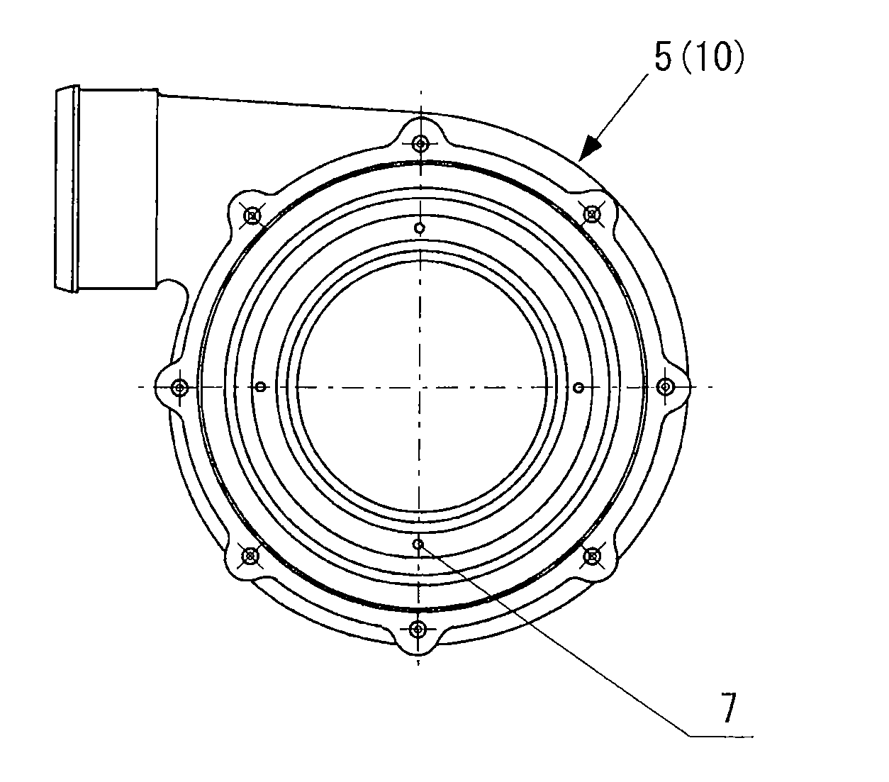
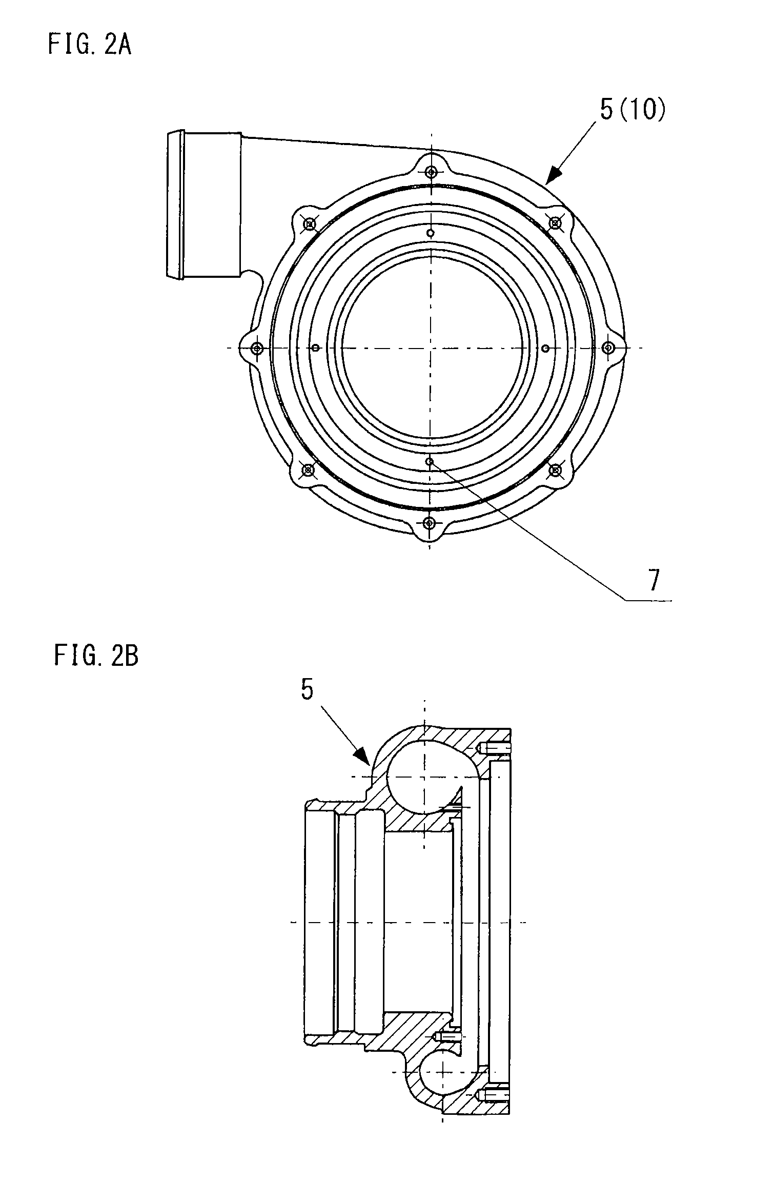
[0042]FIG. 2A, FIG. 2B and FIGS. 3 to 5 schematically illustrate Embodiment 1 of the present invention. FIG. 2A is a schematic front view of a shell 5 of a casing, FIG. 2B is a schematic half cross-sectional view thereof, FIG. 3 is a schematic view of the casing, FIG. 4 is a schematic view of the configuration of a core 6 of the casing, and FIG. 5 is a schematic view of a suction ring groove in the core.

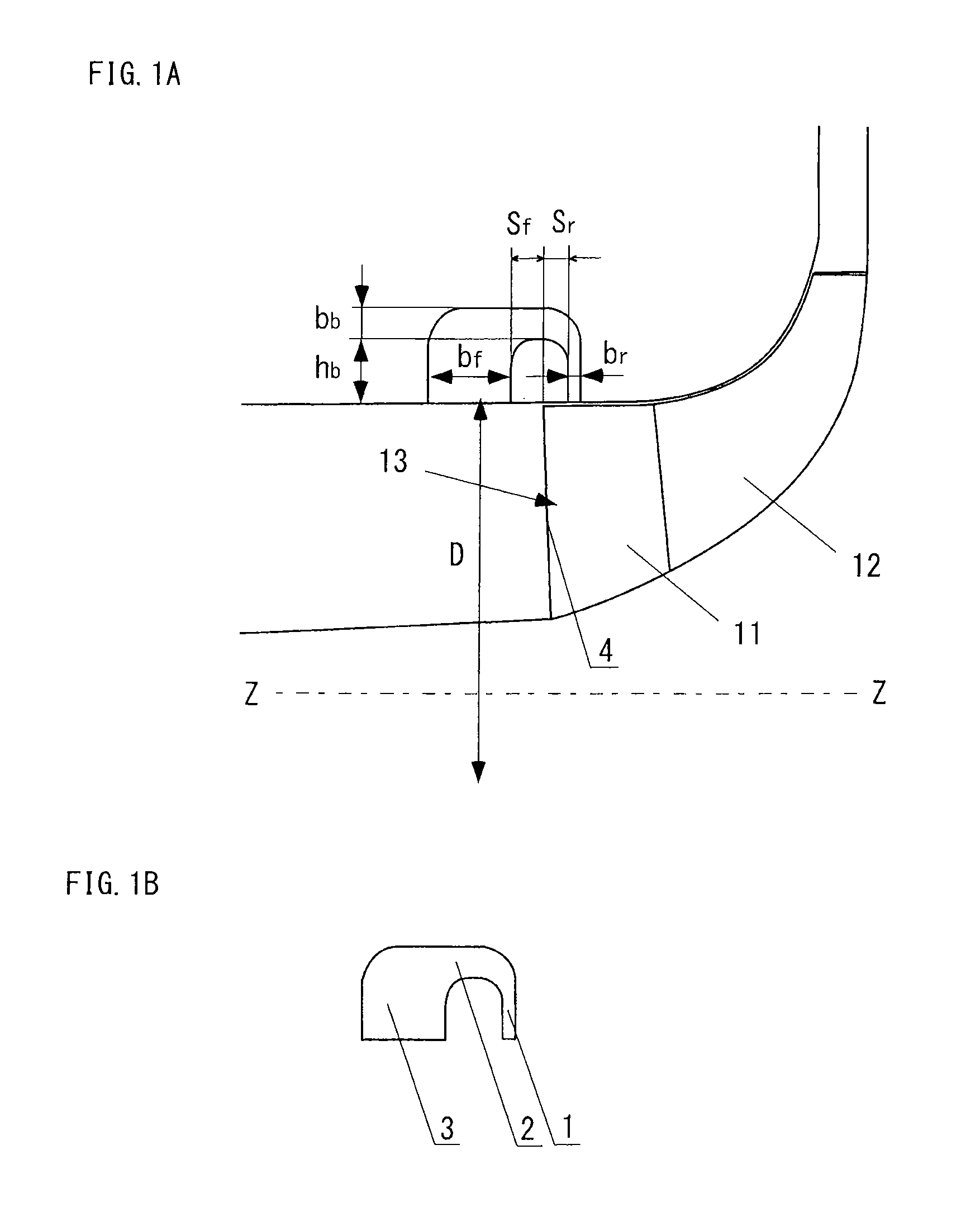
[0043]As illustrated in FIG. 1, the centrifugal compressor of the present invention includes an asymmetric self-recirculating casing treatment that includes, on an inner face of a casing, a suction ring groove 1, a ring guide channel 2 and a back-flow ring groove 3, thus forming a self-recirculating channel.

[0044]The self-recirculating channel means a back-flow channel including the suction ring groove 1, the ring guide channel 2 and the back-flow ring groove 3 so as to return the fluid from a position downstream of an impeller full-blade leading edge to a position upstream of the im...

example 1

[0061]The following describes an example to extend a stable operation range by using an asymmetric self-recirculating casing treatment for a centrifugal compressor having a groove position in a parabolic distribution in a centrifugal compressor of a certain size.

[0062]FIG. 8A illustrates a relationship between a normalized mass flow rate and a pressure ratio in Example 1. FIG. 8B illustrates a relationship between a normalized mass flow rate and efficiency in Example 1.

[0063]FIG. 8A and FIG. 8B illustrate a comparison of compressor performance among an asymmetric self-recirculating casing treatment having a groove position in a parabolic distribution (“asymmetric self-recirculating CT”), a symmetric self-recirculating casing treatment (“symmetric self-recirculating CT”) and without casing treatment (“without CT”).

[0064]The performance comparison between FIG. 8A and FIG. 8B shows that the asymmetric self-recirculating casing treatment having a groove position in a parabolic distribut...

embodiment 2

[0065]FIG. 9 to FIG. 11 schematically illustrate Embodiment 2 of the present invention, where FIG. 9 is a schematic view of a casing 10 of a compressor, FIG. 10 is a schematic view of the configuration of a core 6 of the casing 10, and FIG. 11 is a schematic view of a suction ring groove 1 in the core 6.

[0066]FIG. 2A and FIG. 2B are common to Embodiment 1.

[0067]As illustrated in FIG. 1, the centrifugal compressor of the present invention includes an asymmetric self-recirculating casing treatment that includes, on an inner face of a casing 10, a suction ring groove 1, a ring guide channel 2 and a back-flow ring groove 3, thus forming a self-recirculating channel.

[0068]In the centrifugal compressor of Embodiment 2, as illustrated in FIG. 9, a casing 10 includes a shell 5 and the core 6, where the suction ring groove 1 is provided on a wall face of the core 6, and the inner wall face of the shell 5 and the outer wall face of the core 6 define the ring guide channel 2 and the back-flow ...


PUM


Abstract

A centrifugal compressor includes an asymmetric self-recirculating casing treatment that includes, on an inner face of a casing 10, a suction ring groove 1, a ring guide channel 2 and a back-flow ring groove 3 to form a self-recirculating channel. An axial-direction position Sr from an upstream end face of the suction ring groove to an impeller full blade leading edge 4 or a width br of the suction ring groove 1 is represented as A(α·D−β·D)2+A0 and is distributed in a parabolic shape in a circumferential direction. An initial phase angle θ0 is in a range of 0≦θ0≦2π. A circumferential angle α of the casing has a definition range of θ0≦α≦θ0+2λ. In the expression, A denotes a parameter of the parabola in the axial-direction position Sr or the width br, and A0 denotes an extreme of the axial-direction position Sr or the width br when corresponding circumferential angle β and the α are equal at an extreme point of distribution of the parabola.

Description

TECHNICAL FIELD[0001]The present invention relates to centrifugal compressors including an asymmetric self-recirculating casing treatment. The centrifugal compressors are used in turbomachinery for various purposes such as superchargers for vehicles and ships, industrial compressors and aeroengines.BACKGROUND ART[0002]Although turbo compressors using a centrifugal compressor have advantages such as having better efficiency, being lighter in weight and having more stable in operation than reciprocating compressors, their allowable operating range (i.e., the flow rate range of a centrifugal compressor) is limited.[0003]At a small flow-rate operating point of a centrifugal compressor (i.e., when the flow rate of a compressor is small), instable phenomena such as considerable fluid separation at the internal flow field occur, thus causing stall and accordingly surge. As a result, rapid decrease in the efficiency and the pressure-ratio ratio of the compressor is caused, the life of the c...

Claims


Application Information

Patent Timeline
Patent Type & Authority Applications(United States)
IPC IPC(8): F04D29/42
CPCF04D29/4213F04D29/685F04D17/10
Inventor ZHENG, XINQIANLIN, YUNZHANG, YANGJUNYANG, MINGYANGBAMBA, TAKAHIROTAMAKI, HIDEAKI
Owner IHI CORP
Why Eureka
Try Eureka