Centrifugal Compressor Stability Expansion Method Based on Dual-function Coupling Profiles Controlling Diffuser End Wall

A centrifugal compressor, coupled technology, applied in the direction of machine/engine, mechanical equipment, liquid fuel engine, etc., can solve the problems of reducing the flow loss at the design point, the single form of the concave and convex end wall, and the failure to achieve stability, and achieve delay Rotating stall and surge occurrence, suppressing flow separation, and widening the effect of stable operation range

Active Publication Date: 2022-02-11
XI AN JIAOTONG UNIV
View PDF5 Cites 0 Cited by
  • Summary
  • Abstract
  • Description
  • Claims
  • Application Information

AI Technical Summary

Problems solved by technology

However, this method can only change the peak size of the non-axisymmetric end wall structure, and cannot change the circumferential concave-convex form and the change of the peak along the flow direction, resulting in a single concave-convex end wall form, which cannot realize the diversity of concave-convex end wall forms
Moreover, the shape of the end wall is not selected at the key position of flow instability, which only achieves the purpose of reducing the flow loss at the design point, but fails to achieve the effect of expanding stability.

Method used


Image

  • Centrifugal Compressor Stability Expansion Method Based on Dual-function Coupling Profiles Controlling Diffuser End Wall
  • Centrifugal Compressor Stability Expansion Method Based on Dual-function Coupling Profiles Controlling Diffuser End Wall
  • Centrifugal Compressor Stability Expansion Method Based on Dual-function Coupling Profiles Controlling Diffuser End Wall

Examples


Embodiment Construction

[0037] Exemplary embodiments of the present disclosure will be described in more detail below with reference to the accompanying drawings. Although exemplary embodiments of the present disclosure are shown in the drawings, it should be understood that the present disclosure may be embodied in various forms and should not be limited by the embodiments set forth herein. Rather, these embodiments are provided for more thorough understanding of the present disclosure and to fully convey the scope of the present disclosure to those skilled in the art. It should be noted that, in the case of no conflict, the embodiments of the present invention and the features in the embodiments can be combined with each other. The present invention will be described in detail below with reference to the accompanying drawings and examples.

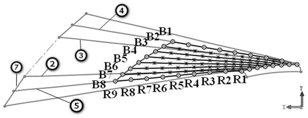
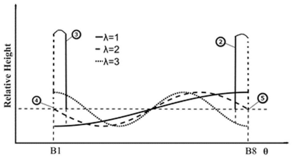
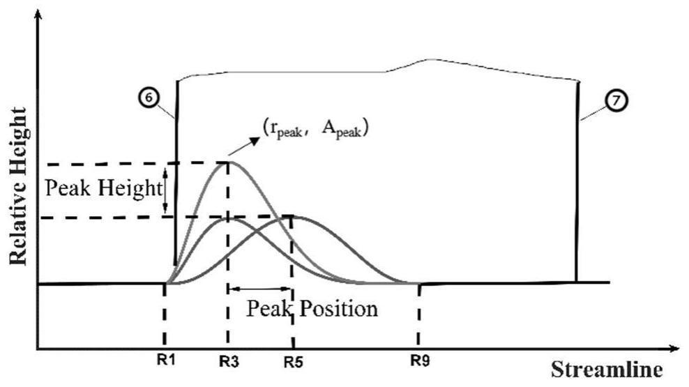
[0038] see Figure 1 to Figure 3 , the present invention applies the modeling method of the end wall of the dual-function coupling surface control diffuser t...


PUM


Abstract

The centrifugal compressor stability expansion method of the double-function coupling surface regulating diffuser end wall of the present invention comprises: firstly, by performing geometric modeling and numerical simulation on the original centrifugal compressor with bladed diffuser, analyzing The flow structure that induces instability, find out the most critical position that induces the sign of compressor stall, and determine the wall of the vane diffuser hub where the sign of stall occurs is determined as the key position of the shape; then, according to the flow law, the conventional planar end wall is transformed into a concave-convex shape The dual-function coupling profile with undulating characteristics can flexibly construct different forms of concave-convex end walls by adjusting the three profile control parameters. periodic array. The invention changes the flow velocity and pressure distribution near the wall by changing the geometric shape of the flow channel, effectively inhibits the flow separation of the centrifugal compressor under the small flow condition, delays the occurrence of rotational stall and surge, and thus broadens the stable operation range of the centrifugal compressor.

Description

technical field [0001] The invention belongs to the technical field of centrifugal compressors, and in particular relates to a method for stabilizing a centrifugal compressor by regulating the end wall of a diffuser with a dual-function coupling profile. Background technique [0002] Due to the advantages of small size, high single-stage pressure ratio and simple structure, centrifugal compressors play a vital role in metallurgy, petrochemical, natural gas transportation, refrigeration, electric power and other industries. With the continuous advancement of the modern industrial process, the development of high-load, wide-range, high-efficiency, and miniaturized centrifugal compressors is one of the current important trends, and more stringent requirements are put forward for the performance of centrifugal compressors. Throughout the research on centrifugal compressors by domestic and foreign scholars, it is found that the design of high-load centrifugal compressors can be r...

Claims


Application Information

Patent Timeline
Patent Type & Authority Patents(China)
IPC IPC(8): F04D17/10F04D29/00F04D29/44G06F30/20
CPCF04D17/10F04D29/444F04D29/002G06F30/20
Inventor 崔琴秦国良王懿贾诚雷健
Owner XI AN JIAOTONG UNIV
Why Eureka
Try Eureka