Eureka AIR delivers breakthrough ideas for toughest innovation challenges, trusted by R&D personnel around the world.

Adhesive pad

Inactive Publication Date: 2012-12-06
CHEN ALBERT
View PDF7 Cites 6 Cited by
  • Summary
  • Abstract
  • Description
  • Claims
  • Application Information

AI Technical Summary

Benefits of technology

[0007]The invention may be embodied in an adhesive pad that may be permanently shaped similar to and sized to receive a small electronic object such as a cell phone, PDA, GPS device, or MP3 player. The pad may have graphics or text embedded there-in or printed thereon that indicate the object that it is intended to receive, and where on the pad that object is intended to be received. The pad may be inherently tacky and thereby adhesive on both its front and back faces, its back face being adapted for adhesion to a wide array of horizontal, vertical, or inclined flat surfaces, and its front face being adapted for adhesion to either a specific or a variety of such electronic objects or equivalent devices. The adhesiveness if the back face to the surface may be sufficient to hold the pad to the surface, whether the surface is vertically or horizontally disposed and to withstand not only the gravitational forces on the object and pad, but also to withstand the removal forces of the object being removed from the front face. The adhesiveness of the front face to the object may be sufficient to retain the object to the pad against the forces of gravity even when the pad is vertically disposed, yet may be weaker than the adhesiveness of the back face, enough to allow removal of the object from the pad without inadvertently peeling the pad from the surface. Alternatively, the graphics may inspire the user to position of the object centrally on the front face so that removal of the object will not cause peeling of the back face from the surface.
[0008]The invention may be embodied in an adhesive pad having an adhesive back layer made of a first oil-impregnated thermoplastic rubber, and an adhesive front layer made of a second oil-impregnated thermoplastic rubber permanently adhered to the back adhesive layer. The first and second oil-impregnated thermoplastic rubbers may be identical. Alternatively, the back and front layers may be permanently affixed to an intermediary layer. The front layer may be transparent and the intermediary layer may include graphics or text viewable through the front layer that indicate a device that the front layer is intended to receive, and / or a location on the front layer where the device is intended to be received. The location on the front layer where the device is intended to be received may be centrally on the front layer. The intermediary layer may additionally provide structural qualities unavailable in the thermoplastic rubbers of the back and front layers. The front layer may have a textured surface to reduce its adhesiveness to the device. The texturing may reduce the adhesiveness of the front layer to below the adhesiveness of the back layer.
[0011]The intermediary layer may additionally provide structural qualities unavailable in the thermoplastic rubbers of the back and front layers. The front layer may have a textured surface to reduce its adhesiveness to the device. The texturing may reduce the adhesiveness of the front layer to below the adhesiveness of the back layer.
[0013]The graphics and / or text may indicate positioning of an object centrally on the front layer so that removal of the object will not cause peeling of the back face from a surface to which the back face is adhered.

Problems solved by technology

The adhesiveness of the front face to the object may be sufficient to retain the object to the pad against the forces of gravity even when the pad is vertically disposed, yet may be weaker than the adhesiveness of the back face, enough to allow removal of the object from the pad without inadvertently peeling the pad from the surface.

Method used


Image

  • Adhesive pad
  • Adhesive pad
  • Adhesive pad

Examples


Embodiment Construction

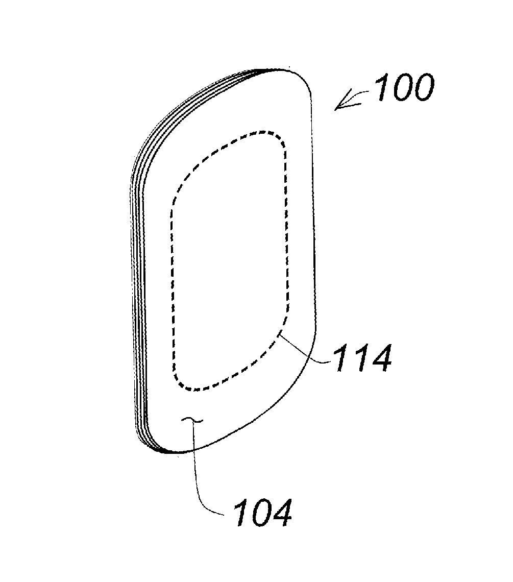
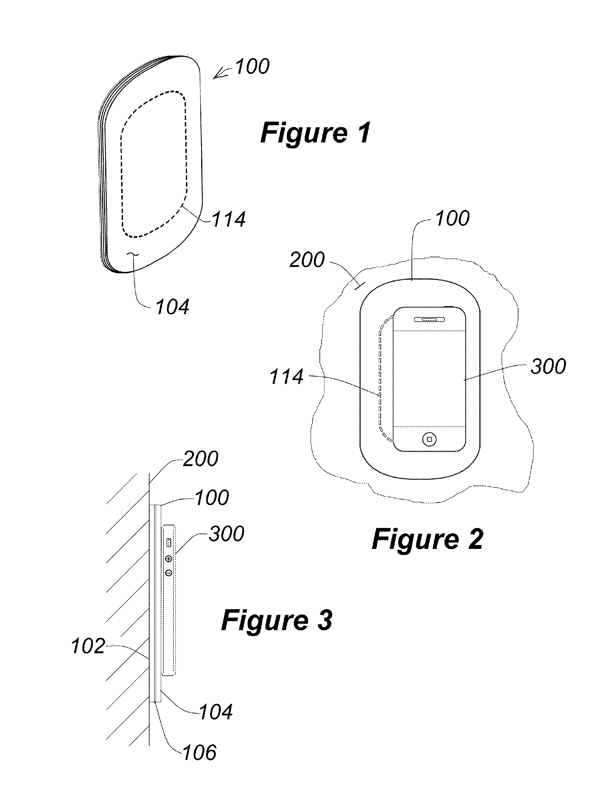
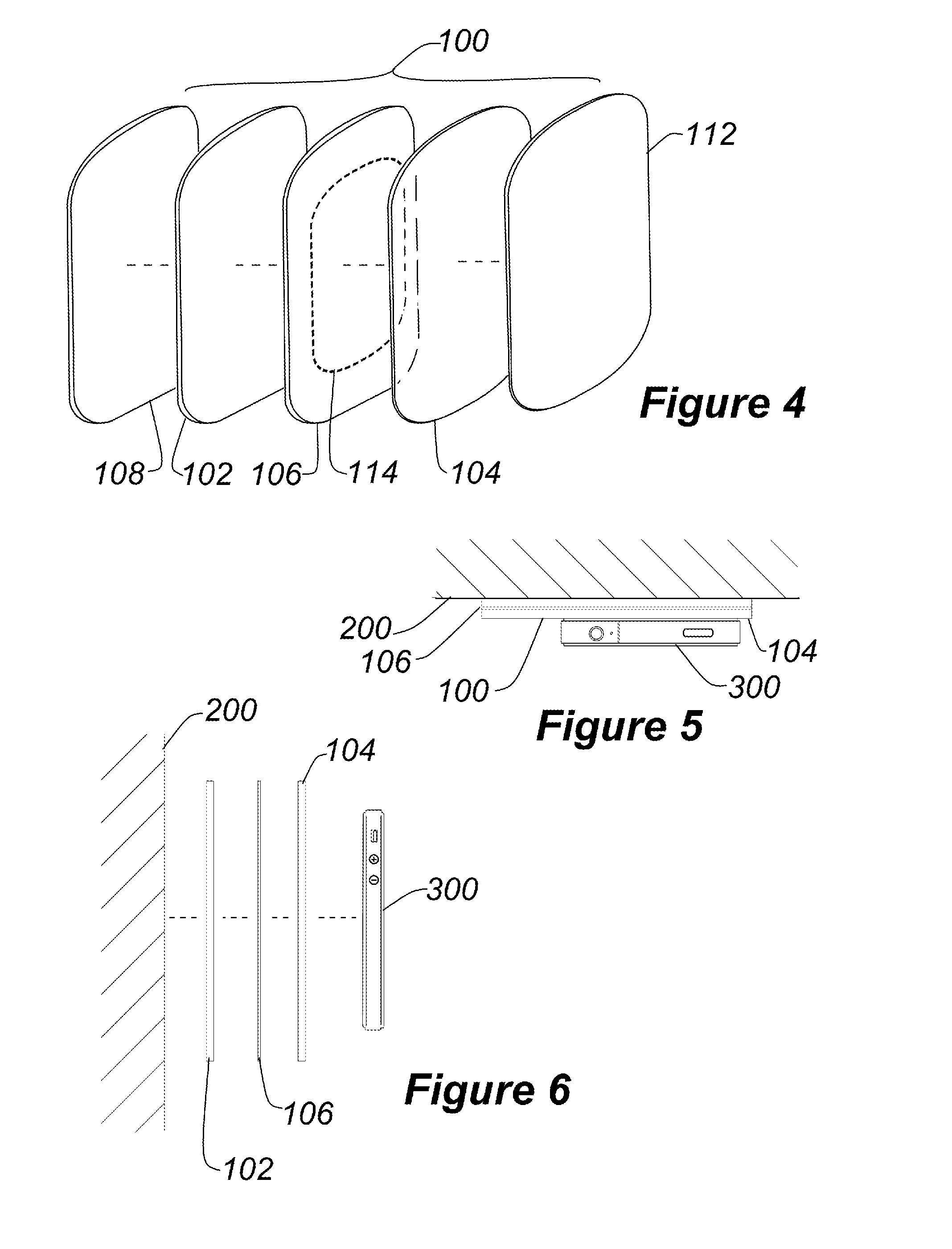
[0023]Referring to FIGS. 1 and 4, an adhesive pad 100 according to an exemplary embodiment of the present invention includes a back adhesive layer 102, a front adhesive layer 104, and an intermediary layer 106. Also included are a back contact sheet 108 and a front contact sheet 112 which are each temporarily adhered to the respective faces of the adhesive sheets during shipping or storage of the adhesive pad.

[0024]The front and back adhesive layers are preferably each made of a homogenous oil-enhanced thermoplastic rubber polymer material (TPR). The preferred material is further described below, but a myriad of similar materials may be substituted therefore, so long as those provide equivalent adherence and removal performance. The qualities of this material may differ in each adhesive layer, as explained below. The front and back adhesive layers are permanently bound to the intermediary layer, preferably by an oil-based adhesive coating 106 there-between. The material of at least ...


PUM

PropertyMeasurementUnit
Fractionaaaaaaaaaa
Fractionaaaaaaaaaa
Fractionaaaaaaaaaa

Abstract

A flexible adhesive pad has a tacky elastomeric back layer made of a first naphthenic oil-impregnated thermoplastic rubber, an intermediary layer made of a polymer film permanently adhered to the elastomeric back layer by a first oil-based adhesive, and a tacky elastomeric front layer made of a second naphthenic oil-impregnated thermoplastic rubber adhered to the intermediary layer by a second oil-based adhesive. The front layer is transparent and the intermediary layer may has graphics or text viewable through the front layer that indicate a device that the front layer is intended to receive, and / or where on the front layer that device is intended to be received.

Description

RELATED APPLICATION[0001]This application is a Continuation-in-Part of pending U.S. Utility patent application Ser. No. 13 / 152,312, filed on Jun. 3, 2011, the entire teachings thereof being incorporated herein by reference.FIELD OF THE INVENTION[0002]The present invention is generally related to adhesive pads. More specifically, the field of the invention as embodied in the present disclosure is related to a planar pad that is adhesive on both faces to most surfaces, is removable there-from without leaving residue behind, has use-indicative graphics or text, and is reusable. Even more specifically, the field of the invention as embodied in the present disclosure is related to such a double-sided reusable sheet that is adhesive enough to removably and repeatedly adhere such massive items as cell phones, personal digital assistants (PDAs), GPS devices, and MP3 players to a vertical surface, in which the items are more easily removed from the pad than the pad is removed from the surfac...

Claims


Application Information

Patent Timeline
IPC IPC(8): C09J7/02C09J109/06C09J115/00B32B7/12B32B3/10C09J7/10
CPCB32B7/12Y10T428/2852B32B27/302C08K5/0016C08K5/01C08K5/02C09J7/00C09J7/021B32B2274/00B32B2307/412B32B2307/75C09J2201/128C09J2201/134C09J2201/36C09J2205/102C09J2423/046C09J2453/00C09J2467/006C09J2469/006C09J109/06C09J153/02Y10T428/2878Y10T428/24802Y10T428/2848Y10T428/2883B32B27/08C09J7/381C09J7/10C09J2301/1242C09J2301/208C09J2301/124C09J2301/408
Inventor CHEN, ALBERT
Owner CHEN ALBERT
Why Eureka
Eureka Blog
Learn More