
Reconstrainable stent delivery system

a stent and stent technology, applied in the field of constraining stents and delivery systems, can solve the problems of stents that foreshorten an appreciable amount, stents that are placed in incorrect or suboptimal locations are subject to more difficulties, stents may be subject to substantial flexing or bending, axial compression and repeated displacement,

Inactive Publication Date: 2012-12-06
FLEXIBLE STENTING SOLUTIONS
View PDF6 Cites 25 Cited by
  • Summary
  • Abstract
  • Description
  • Claims
  • Application Information

AI Technical Summary

Benefits of technology

"The present invention is a catheter delivery system for self-expanding stents that can be easily deployed in the treatment of vascular disease. The system includes a slider, pusher, and a spring element that work together to move the stent in a distal direction as it is deployed. The system also includes a gripper for easy handling and a housing to grip the stent. The stent is made from a helical strut band and coil elements that provide flexibility, stability, and radial strength. The stent can be easily crimped and released from the catheter. The invention also includes a spring element that maintains the stent in a tensioned state during reconstraining. The stent can be used in various vascular disease states such as iliac, femoral, popliteal, carotid, and neurovascular arteries."

Problems solved by technology

Most commercial self expanding stents are not designed to be recaptured (reconstrained) into the delivery system once the stent has started to expand into the target vessel, artery, duct or body lumen.
Stents that foreshorten an appreciable amount are subject to more difficulties when being deployed in a body lumen or cavity, such as a vessel, artery, vein, or duct.
Foreshortening may lead to a stent being placed in an incorrect or suboptimal location.
Yet, after deployment, in certain applications, a stent may be subjected to substantial flexing or bending, axial compressions and repeated displacements at points along its length, for example, when stenting the superficial femoral artery.
This can produce severe strain and fatigue, resulting in failure of the stent.
A similar problem exists with respect to stent-like structures.

Method used


Image

  • Reconstrainable stent delivery system
  • Reconstrainable stent delivery system
  • Reconstrainable stent delivery system

Examples


Embodiment Construction

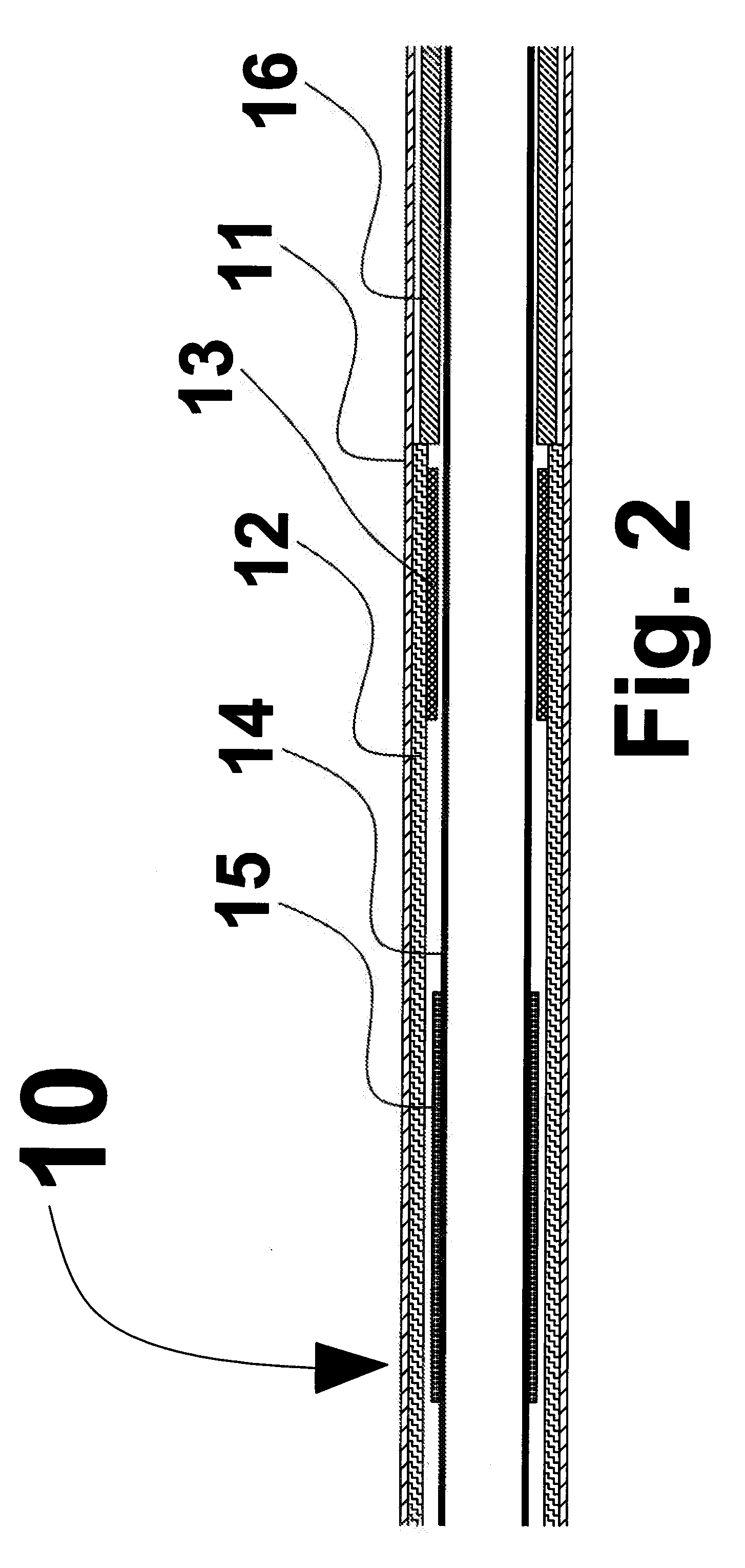
[0048]Self expanding stent delivery system 10 of the present invention is shown in FIG. 1. The outer tube which is also known as outer sheath 11, constrains stent 12 in a crimped or radially compressed state. The inner members can be comprised of multiple components including distal tip 8, guide wire tube 14 and pusher 16 to react the axial forces placed on the stent as outer sheath 11 is retracted to deploy stent 12. Pusher 16 can also act as a proximal stop. Other elements of self expanding stent delivery system 10 can include luer lock hub 6 attached to the proximal end of pusher 16 and handle 3 attached to outer sheath 11. Handle 3 incorporates luer port 4 such that the space between the inner members and outer sheath 11 can be flushed with a solution, such as a saline solution, to remove any entrapped air. Pusher 16 can be formed of a composite structure of multiple components, such as a stainless steel tube at the proximal end and a polymer tube inside outer sheath 11.

[0049]St...


PUM


Abstract

The reconstrainable stent delivery system of the present invention comprises a proximal end and distal end which include inner and outer members. A pusher is positioned at the proximal end of the inner member. A slider is located coaxially with the inner member and is positioned within the inner diameter of the stent. The slider can rotate about and move longitudinally along one of an inner shaft or tube, such as the guide wire tube, such that the proximal end of the stent can move distally as the stent deploys. A pusher can be used on the guide wire tube such that the guide wire tube, pusher, and stent move proximally relative to the outer sheath and re-constrain the stent in the outer sheath. Furthermore, the pusher and guide wire tube could move distally as the outer sheath retracts proximally for stent deployment to accommodate foreshortening.

Description

CROSS REFERENCE TO RELATED APPLICATION[0001]This application is a continuation-in-part of U.S. patent application Ser. No. 12 / 573,527 filed Oct. 5, 2009. This application claims the benefit of U.S. Provisional Patent Application No. 61 / 496,376, filed Jun. 13, 2011, the entireties of which applications are hereby incorporated by reference into this application.BACKGROUND OF THE INVENTION[0002]1. Field of the Invention[0003]This invention pertains to a self expanding stent and delivery system for a self expanding stent. The delivery system allows for reconstraining the stent into the delivery catheter simultaneously allowing the stent to change lengths and rotate inside the delivery catheter if required. This invention also pertains to a delivery system for self expanding stent that foreshortens an appreciable amount, for example more than about 10%.[0004]2. Description of the Related Art[0005]Most commercial self expanding stents are not designed to be recaptured (reconstrained) into...

Claims


Application Information

Patent Timeline
Patent Type & Authority Applications(United States)
IPC IPC(8): A61F2/84A61F2/82
CPCA61F2/88A61F2/91A61F2/915A61F2/95A61F2/966A61F2230/0054A61F2002/91575A61F2002/9505A61F2002/9534A61F2002/9665A61F2002/91558
Inventor BEACH, BRADLEYBURPEE, JANETFILACHEK, ANDREWKALAVALAPALLY, RAJESHSHAH, NEELJAEGER, DANA
Owner FLEXIBLE STENTING SOLUTIONS
Learn More