
Percutaneous transcatheter repair of heart valves via trans-apical access

a technology of transcatheter and heart valve, which is applied in the field of treating and repairing heart valves, can solve the problems of long and difficult recovery, preventing the valve from sealing properly, and affecting the recovery of patients in less than optimal health

Active Publication Date: 2012-12-06
VALCARE INC
View PDF5 Cites 152 Cited by
  • Summary
  • Abstract
  • Description
  • Claims
  • Application Information

AI Technical Summary

Benefits of technology

"The patent describes a method for repairing heart valves by delivering and fixing an annuloplasty ring to the heart through a guiding sheath. The method involves compressing the annuloplasty ring and delivering it through the guiding sheath to the heart. The annuloplasty ring is then expanded and secured to the heart valve using anchors. The technical effects of this invention include improved heart valve repair with reduced risk and improved outcomes."

Problems solved by technology

This causes the valve opening to enlarge, which prevents the valve from sealing properly.
The procedure can expose the patient to high risk of infection and may result in a long and difficult recovery.
The recovery can be particularly difficult for patients in less than optimal health due to the effects of suffering from a heart valve defect such as regurgitation.

Method used


Image

  • Percutaneous transcatheter repair of heart valves via trans-apical access
  • Percutaneous transcatheter repair of heart valves via trans-apical access
  • Percutaneous transcatheter repair of heart valves via trans-apical access

Examples


example anchor

[0070 Deployment Mechanism

[0071]FIG. 10 illustrates an annuloplasty ring anchor deployment system 1000, according to one embodiment. In the illustrated embodiment, the annuloplasty ring 1002 includes a plurality of fish hook shaped, curved anchors 1004. Each of the plurality of anchors 1004 includes a laser hole (not shown), or other eyelet-type opening, on the anchor 1004. A suture 1006 may be coupled to the laser hole of each of the anchors 1004. The sutures 1006 may be formed of, for example, nylon, prolene, or the like. The plurality of sutures 1006 coupled to the laser hole may pass through the guiding sheath and out of the patient's body where they can be manipulated by a practitioner. For example, the practitioner may be able to pull the sutures 1006 to deploy the anchors and / or to drive the tips of the anchors into tissue.

[0072]A knot pusher 1008 may be disposed on the sutures 1006 to knot and cut the sutures 1006 once the anchors are deployed. With the annuloplasty ring for...

example ring

[0108 Embodiments with Linear Anchors

[0109]FIG. 16A is a schematic diagram illustrating a perspective view of a segmented annuloplasty ring 1600 including a plurality of linear anchors 1610 according to one embodiment. Seven linear anchors 1610 are shown. However, artisans will understand from the disclosure herein that more linear anchors 1610 or fewer linear anchors may be used. For example, certain embodiments may use ten or more linear anchors 1610.

[0110]The segmented annuloplasty ring 1600 includes a plurality of segments 1612 at least partially cut into a shape memory hypotube that forms a “D-shape” in the annular operable geometry (e.g., when implanted around the annulus) and may be compressed into a compressed delivery geometry for implanting the ring 1600 within a patient's heart through a catheter. As discussed above with respect to FIG. 11, the ring 1600 may also include a ring closure lock 1614 (shown in a connected or locked position) for snap locking the two ends of th...


PUM


Abstract

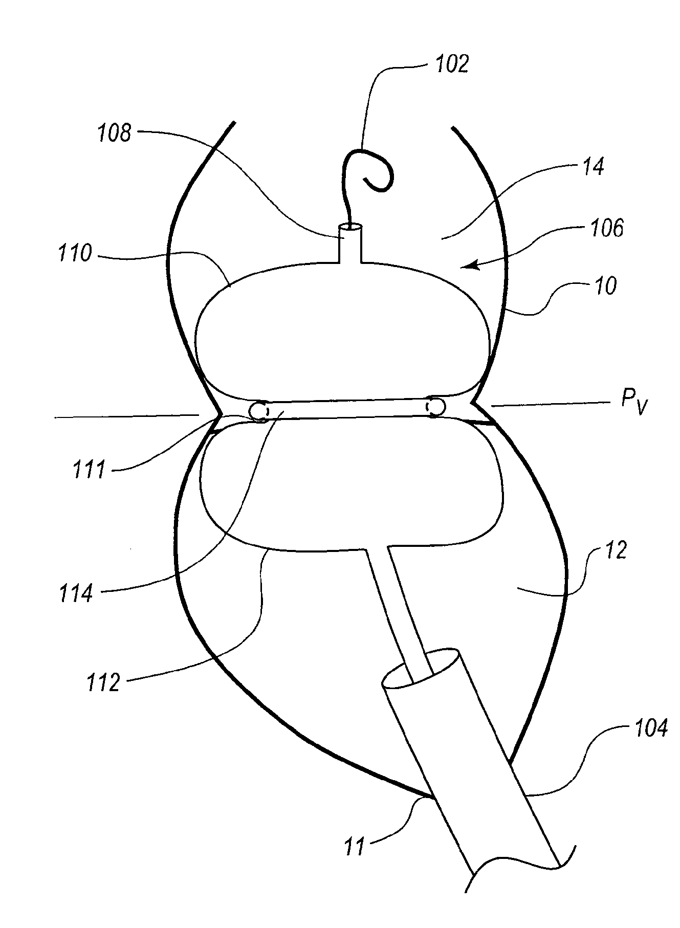
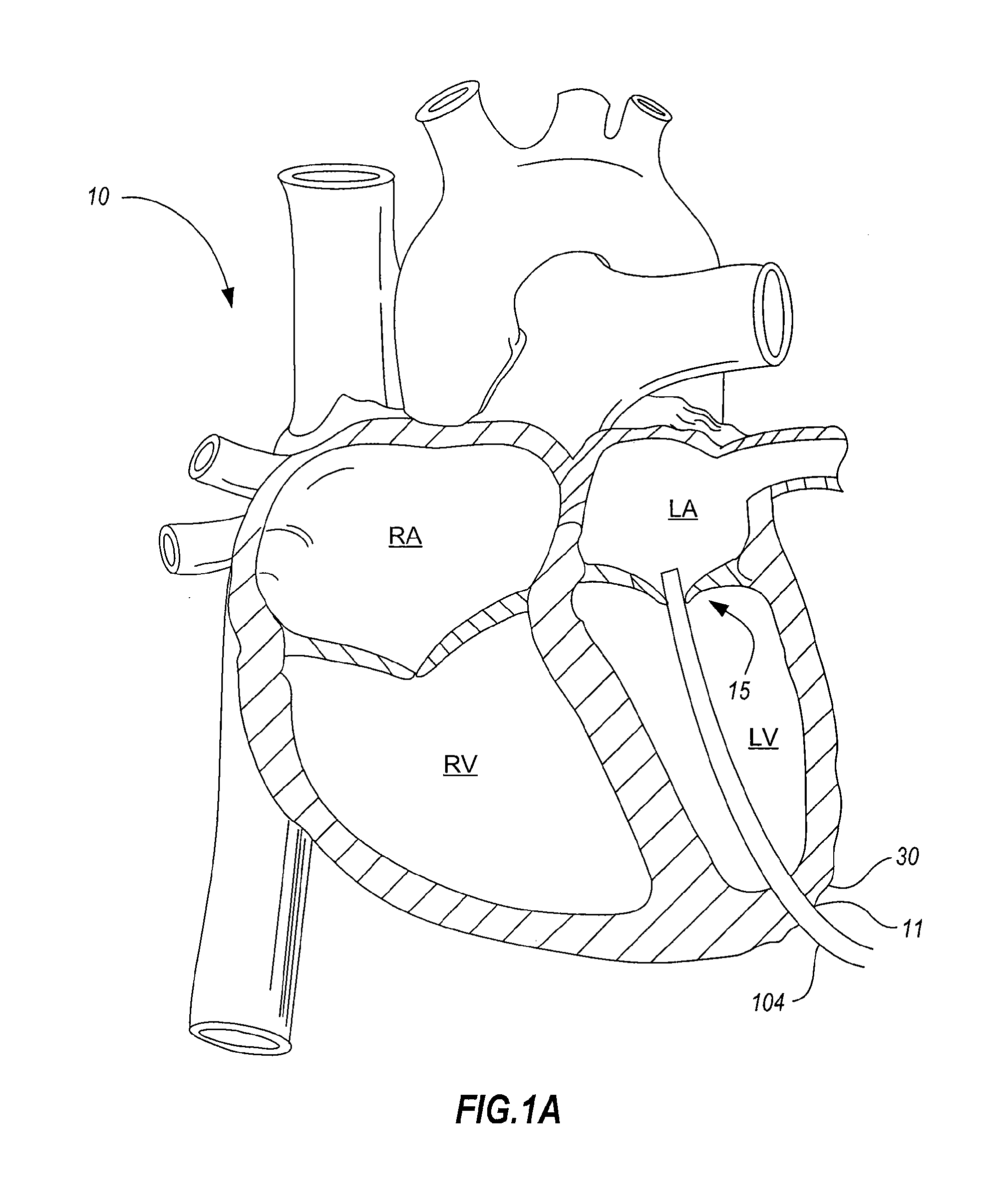
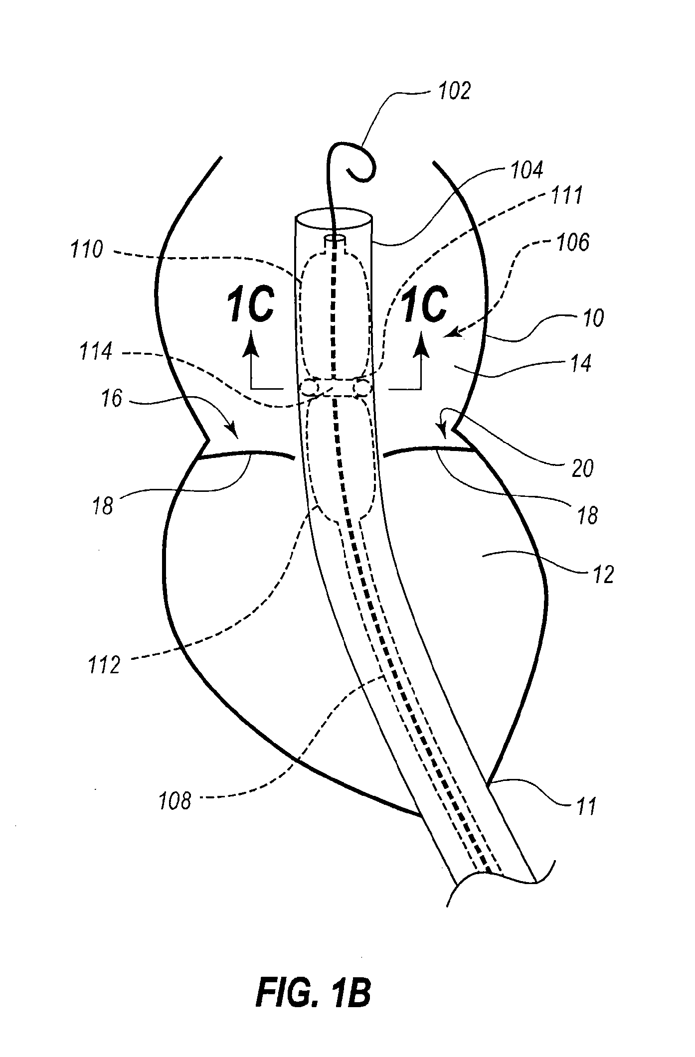
Apparatus, systems, and methods are provided for repairing heart valves through percutaneous transcatheter delivery and fixation of annuloplasty rings to heart valves via a trans-apical approach to accessing the heart. A guiding sheath may be introduced into a ventricle of the heart through an access site at an apex of the heart. A distal end of the guiding sheath can be positioned retrograde through the target valve. An annuloplasty ring arranged in a compressed delivery geometry is advanced through the guiding sheath and into a distal portion of the guiding sheath positioned within the atrium of the heart. The distal end of the guiding sheath is retracted, thereby exposing the annuloplasty ring. The annuloplasty ring may be expanded from the delivery geometry to an operable geometry. Anchors on the annuloplasty ring may be deployed to press into and engage tissue of the annulus of the target valve.

Description

RELATED APPLICATIONS[0001]This application claims the benefit under 35 U.S.C. §119(e) of U.S. Provisional Patent Application No. 61 / 492,279, filed Jun. 1, 2011, and titled “TRANSCATHETER FIXATION OF ANNULOPLASTY RINGS,” which is hereby incorporated herein by reference in its entirety.TECHNICAL FIELD[0002]The present disclosure relates to treating and repairing heart valves, and specifically to apparatus, systems, and methods for percutaneous transcatheter delivery and fixation of annuloplasty rings to repair heart valves. Disclosed embodiments are configured to be delivered through a catheter using a trans-apical approach.BACKGROUND INFORMATION[0003]Heart valve defects, such as regurgitation, may be caused by a relaxation of the tissue surrounding a heart valve (e.g., the mitral valve or tricuspid valve). This causes the valve opening to enlarge, which prevents the valve from sealing properly. Such heart conditions are commonly treated by a procedure during which an annuloplasty rin...

Claims


Application Information

Patent Timeline
Patent Type & Authority Applications(United States)
IPC IPC(8): A61F2/24
CPCA61F2210/0033A61F2/2433A61F2220/0016A61F2/2466A61F2/2448A61F2210/0014A61F2210/0066A61F2210/0023A61F2220/0025A61F2220/0075A61F2230/0006A61F2230/0008A61F2/2442A61F2/95A61F2/958A61F2/2445A61B17/8855A61B2018/0025A61F2250/001A61M2025/1047A61M2025/1072A61M2025/1061A61B17/0469A61B2017/0474A61M25/1011
Inventor BUCHBINDER, MAURICESHAOLIAN, SAMUEL M.
Owner VALCARE INC
Learn More