Stabilizing prosthesis support structure

Active Publication Date: 2012-12-06
ZIMMER INC
View PDF6 Cites 50 Cited by
  • Summary
  • Abstract
  • Description
  • Claims
  • Application Information

AI Technical Summary

Benefits of technology

[0023]Support structures according to the invention may be used to restore the joint line of the natural knee where a large amount of the proximal tibia has been resected to remove correspondingly large amounts of diseased, damaged or otherwise defective bone stock. The combination of platforms into a single monolithic structure with medullary portions, ensures that this joint line is maintained over a long period of time by providing a large bone-contacting surface area. In addition, this monolithic combination presents many bone-contacting faces, each of which are oriented in a different direction with respect to the others to yield a “3-dimensional” or multi-faceted profile of bone-contacting faces. This 3-dimensional profile facilitates multidirectional stabilization of the support structure, and of the tibial baseplate mounted thereto, thereby minimizing or eliminating subsidence, anteroposterior movement and medial-lateral movement of the tibial prosthesis in vivo. Moreover, it has been found that the stability provided by a monolithic support structure made in accordance with the present disclosure provides greater stability than would otherwise be provided by a separate tibial cone-shaped implant and a plate-shaped tibial augment implant, whether used in combination or alone.
[0024]Advantageously, a support structure made in accordance with the present disclosure does not require the use of cement for fixation to a bone. This lack of cement facilitates bone ingrowth by allowing bone to interdigitate more deeply with the porous bone contacting surfaces of the platform. This deep bone ingrowth provides stronger and more secure fixation than could be expected from adhesion between bone cement and bone. Thus, a support struc

Problems solved by technology

However, in some cases the proximal tibia or distal femur may have severe degeneration, trauma, or other pathology which necessitates resection of more bone than can be compensated for by traditional femoral and tibial components.
In the proximal tibia, poor quality bon

Method used


Image

  • Stabilizing prosthesis support structure
  • Stabilizing prosthesis support structure
  • Stabilizing prosthesis support structure

Examples


Example

[0071]Corresponding reference characters indicate corresponding parts throughout the several views. The exemplifications set out herein illustrate exemplary embodiments of the present invention, and such exemplifications are not to be construed as limiting the scope of the invention in any manner.

DETAILED DESCRIPTION

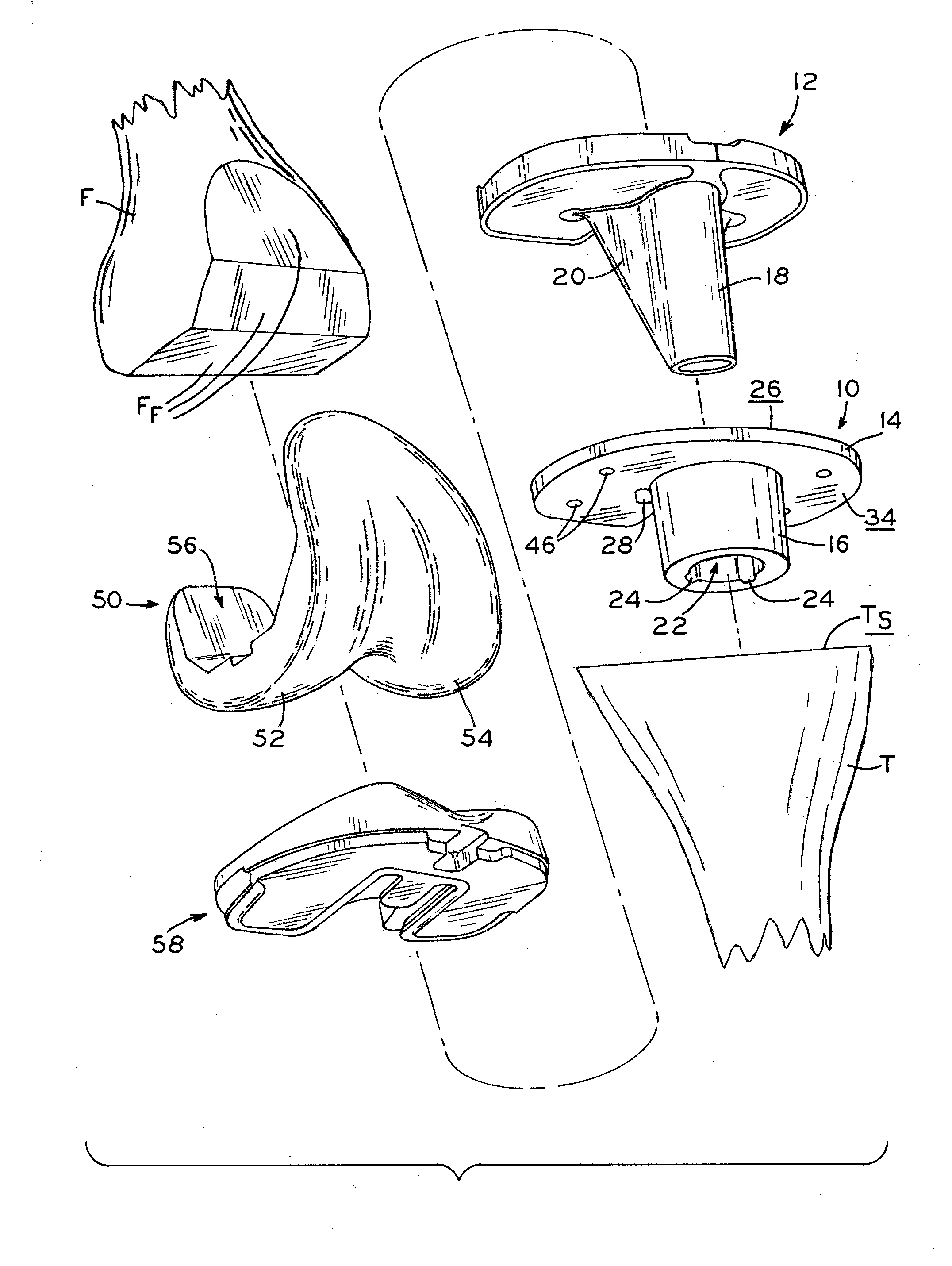
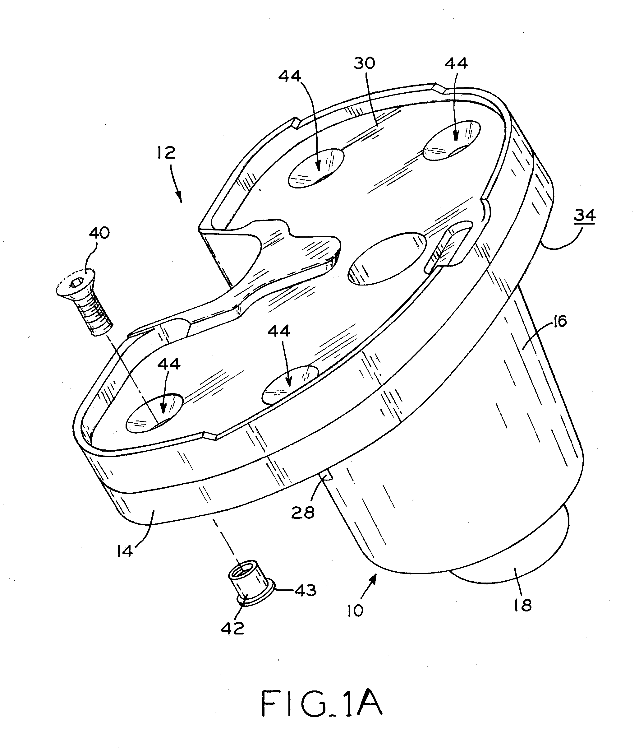
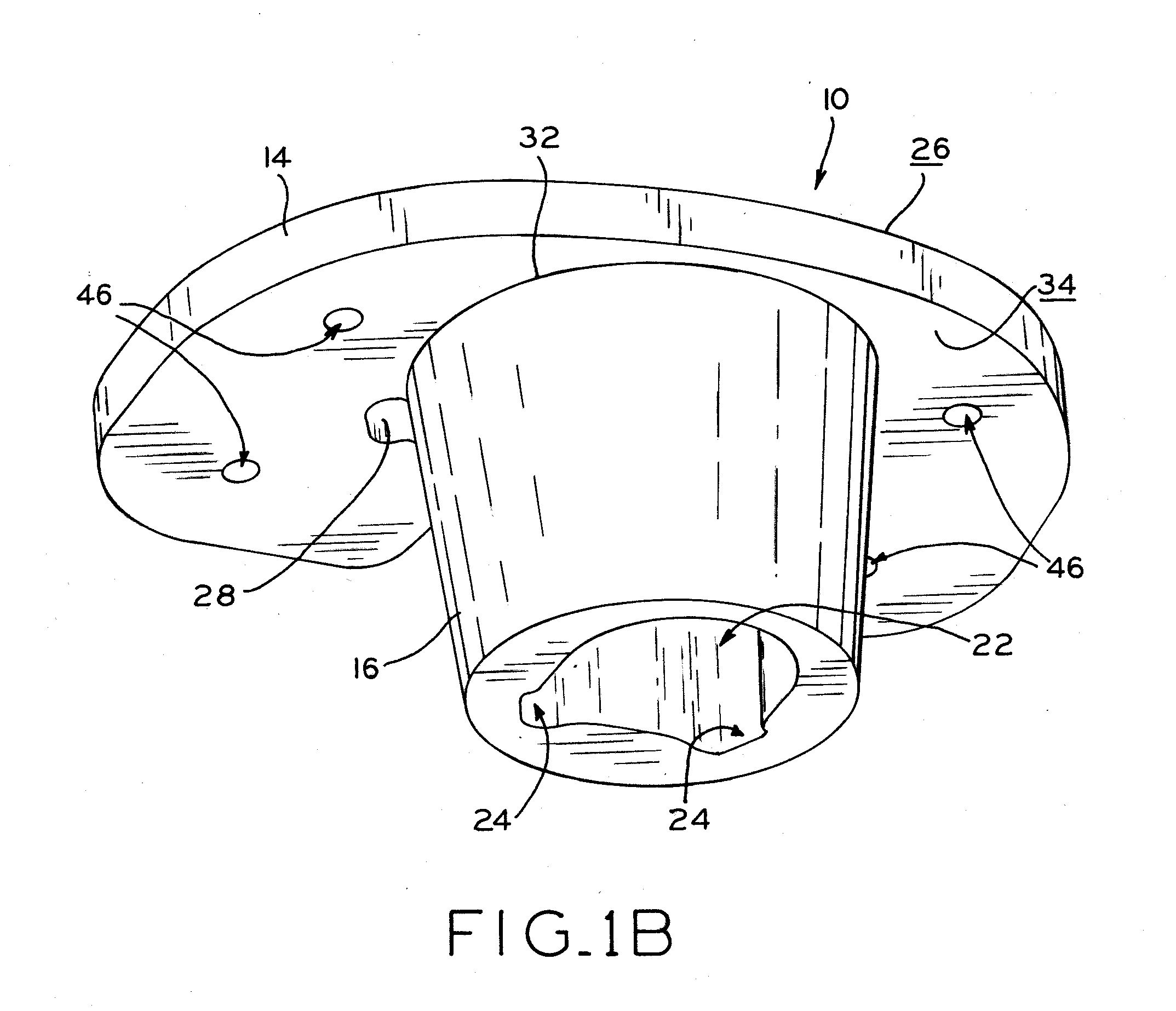
[0072]The present disclosure provides a monolithic implant support structure which provides a stable implant mounting surface in a severely damaged or diseased bone. In the exemplary embodiments discussed below, the support structure provides a foundation for supporting a tibial baseplate that is resistant to subsidence while also facilitating replacement and / or augmentation of metaphyseal or diaphyseal bone within the tibia. The support structure may be made of a porous bone ingrowth material that provides a scaffold for bone ingrowth on multiple surfaces. These surfaces present large, three-dimensional areas of bone ingrowth material to the surrounding healthy bone for...


PUM


Abstract

A tibial support structure includes a platform portion and a medullary portion that are monolithically formed as a single piece. The medullary and platform portions of the augment component are adapted to accommodate and mechanically attach to a tibial baseplate, and are individually shaped and sized to replace damaged bone stock both within the tibia, as well at the tibial proximal surface. The monolithic formation of the tibial support structure provides a strong and stable foundation for a tibial baseplate and facilitates restoration of the anatomic joint line, even where substantial resections of the proximal tibia have been made. The tibial support structure may be made of a bone-ingrowth material which facilitates preservation and rebuilding of the proximal tibia after implantation, while also preserving the restored joint line by allowing revision surgeries to be performed without removal of the tibial support structure.

Description

CROSS-REFERENCE TO RELATED APPLICATION[0001]This application claims the benefit under Title 35, U.S.C. §119(e) of U.S. Provisional Patent Application Ser. No. 61 / 488,549, filed May 20, 2011 and entitled STABILIZING PROSTHESIS SUPPORT STRUCTURE, the entire disclosure of which is hereby expressly incorporated herein by reference.BACKGROUND[0002]1. Technical Field[0003]The present disclosure relates to orthopaedic prostheses, and more particularly, to stabilized tibial support structures for use with a knee prosthesis.[0004]2. Description of the Related Art[0005]Orthopaedic prostheses are commonly utilized to repair and / or replace damaged bone and tissue in the human body. For example, a knee prosthesis may be used to restore natural knee function by repairing damaged or diseased articular surfaces of the femur and / or tibia. Knee prostheses may include a femoral component implanted on the distal end of the femur, which articulates with a tibial component implanted on the proximal end o...

Claims


Application Information

Patent Timeline
IPC IPC(8): A61F2/38
CPCA61F2/30734A61F2/389A61F2002/3051A61F2250/0063A61F2002/30616A61F2002/30884A61F2002/3092A61F2002/30512A61F2002/30507
Inventor ZUBOK, RAYMONTOYA, JORGEHOEMAN, TIMOTHY A.CHERNOSKY, JOHNROBY, KEITH A.
Owner ZIMMER INC
Why Eureka
Try Eureka