Stirling Engine Systems, Apparatus and Methods

a technology of engine and steam engine, applied in the direction of solar heat devices, solar-ray concentration, lighting and heating apparatus, etc., can solve the problems of high production cost of current photovoltaic-based systems, and achieve the effects of reducing the rate, reducing the amount of solar radiation, and prolonging the use-life of solar heat exchangers

Inactive Publication Date: 2012-12-13
QNERGY
View PDF6 Cites 9 Cited by
  • Summary
  • Abstract
  • Description
  • Claims
  • Application Information

AI Technical Summary

Benefits of technology

[0005]In one embodiment, the invention relates to a mechanical assembly that includes a solar energy collector, typically a reflective surface or an array of mirrors, and an energy converting apparatus. In one embodiment, the energy converting apparatus includes a Stirling cycle engine. A free-piston Stirling engine embodiment can be configured such that both the collector and the energy converting apparatus are elevated relative to the ground on a pier to enable better solar energy collection and engine positioning.
[0032]One embodiment provides a method for improving performance of an energy converter system. The method can include the steps of: providing a heat exchanger having a surface area for absorbing thermal energy; concentrating thermal energy on a portion of the surface area of the heat exchanger, and moving the concentrated thermal energy about the surface area of the heat exchanger, thereby reducing thermal input, spreading hot spots, reducing the rate at which the heat exchanger heats, and / or maintaining coolant temperature.

Problems solved by technology

Current photovoltaic-based systems are expensive to produce and take from one to twenty years to generate the amount of power required for their own production.

Method used


Image

  • Stirling Engine Systems, Apparatus and Methods
  • Stirling Engine Systems, Apparatus and Methods
  • Stirling Engine Systems, Apparatus and Methods

Examples


Embodiment Construction

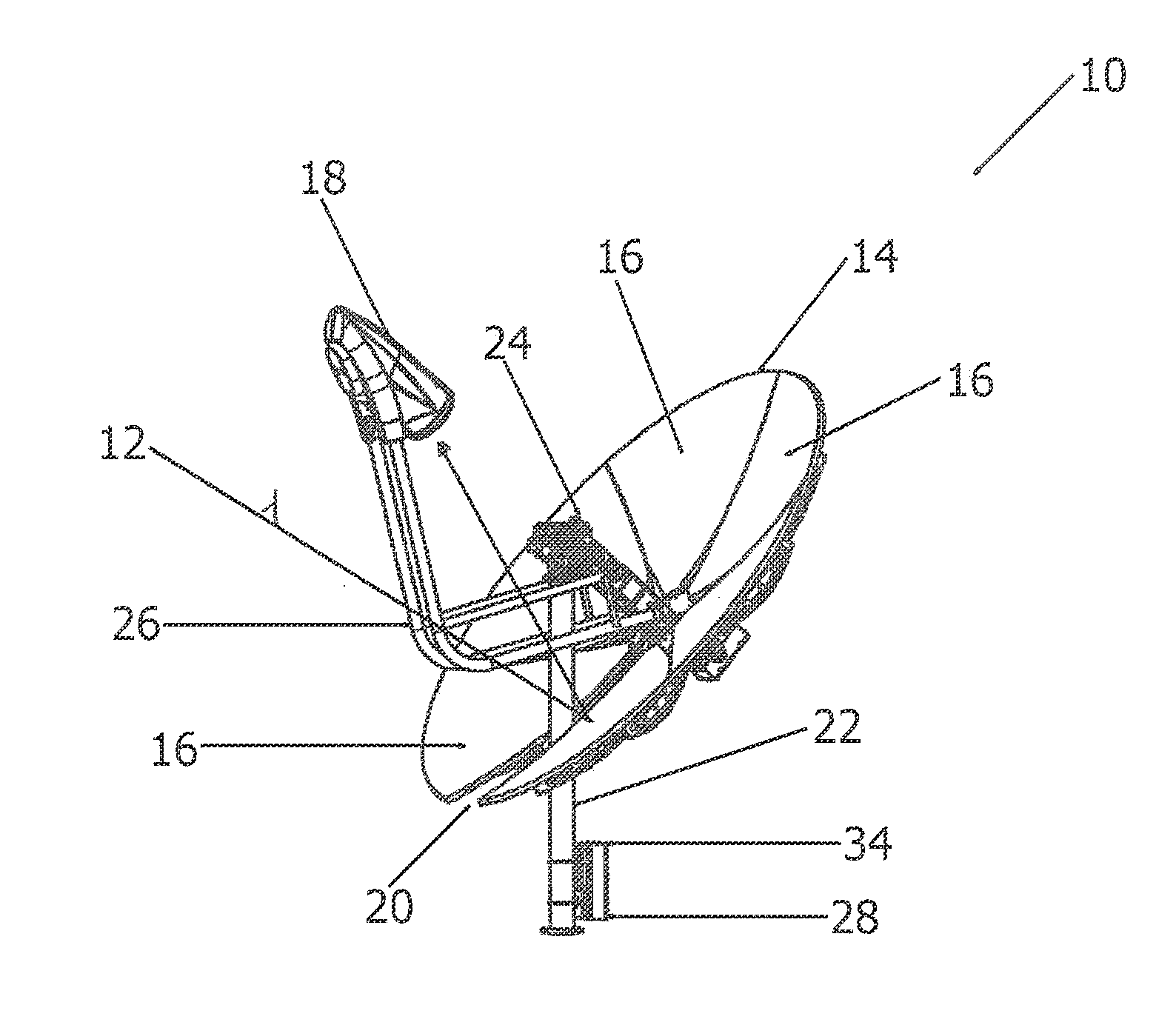
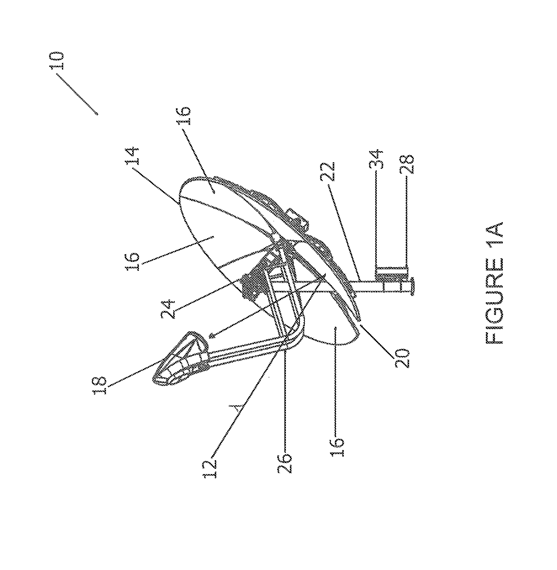
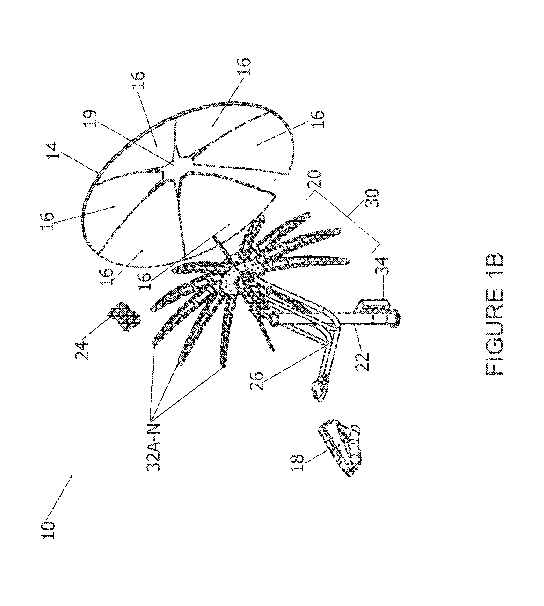
[0065]The following description refers to the accompanying drawings that illustrate certain embodiments of the present invention. Other embodiments are possible and modifications may be made to the embodiments without departing from the spirit and scope of the invention. Therefore, the following detailed description is not meant to limit the present invention, rather the scope of the present invention is defined by the claims.

[0066]The use of sections or headings in the application is not meant to limit the invention each section and heading can apply to any aspect, embodiment, or feature of the invention.

[0067]It should be understood that the order of the steps of the methods of the invention is immaterial so long as the invention remains operable. Moreover, two or more steps may be conducted simultaneously or in a different order than recited herein unless otherwise specified.

[0068]Where a range or list of values is provided, each intervening value between the upper and lower limi...


PUM

PropertyMeasurementUnit
diameteraaaaaaaaaa
diameteraaaaaaaaaa
diameteraaaaaaaaaa

Abstract

Systems, methods, and apparatus relating to the use of Stirling engine technology to convert heat, such as from solar radiation, to mechanical work or electricity. Apparatus, systems, components, and methods relating to energy converting apparatus are described herein. In one aspect, the invention relates to the field alignment of panels and the assembly of a concentrator. In another aspect, a passive balancer is used in combination with a ring frame and other moving masses to reduce engine forces and vibration on the structure of the energy converting apparatus while maintaining properly constrained alignment of various suspended masses. In yet another aspect, the invention relates to various over-insolation control and management strategy to prevent overheating of the energy converting apparatus or components and subsystems thereof.

Description

CROSS REFERENCE TO RELATED APPLICATIONS[0001]This application claims priority to and the benefit of U.S. Provisional Application No. 61 / 104,915, filed Oct. 13, 2008, and U.S. Provisional Application No. 61 / 196,042, filed Oct. 13, 2008, the entire disclosures of each of which are hereby incorporated by reference herein for all purposes.FIELD OF THE INVENTION[0002]The invention relates generally to the field of energy converting devices such as Stirling engines. Specifically, the invention relates to devices, systems, subsystems, components and methods that facilitate the collection and conversion of solar and other types of energy.BACKGROUND OF THE INVENTION[0003]Current photovoltaic-based systems are expensive to produce and take from one to twenty years to generate the amount of power required for their own production. Accordingly, a need exists for other energy converting technologies that are competitive with or otherwise superior to photovoltaic-based approaches.SUMMARY OF THE I...

Claims


Application Information

Patent Timeline
Patent Type & Authority Applications(United States)
IPC IPC(8): F03G6/06F02G1/055F02G1/043F24J2/46F24J2/10F24S23/70
CPCF03G6/068Y10T29/49895Y02E10/46Y02T10/7072
Inventor FRASER, PAULSMITH, TERRYLUONGO, ROCCOTHURGOOD, JUSTINWETHERBEE, TRENTMILLERET, RAPHAELPETERSON, ALLENAUGENBLICK, JOHN EDWARDMCCALLUM, SCOTTWILLIFORD, IANERBEZNIK, RAYGYORI, BENFOX, PATRICKMCVICKER, HARRYDALE, TINA
Owner QNERGY
Why Eureka
Try Eureka