Inspection device and method for positioning an inspection device

a technology of inspection device and inspection device, which is applied in the direction of applications, lighting and heating apparatus, instruments, etc., can solve the problems of only functional link joints, inconvenient use of stationary gas turbines, and difficulty in inspecting annular combustion chambers, so as to increase the availability and flexibility of gas turbines or combustion chambers, quick and easy access to inspection, and reduce inspection time

Inactive Publication Date: 2012-12-13
SIEMENS AG
View PDF11 Cites 43 Cited by
  • Summary
  • Abstract
  • Description
  • Claims
  • Application Information

AI Technical Summary

Benefits of technology

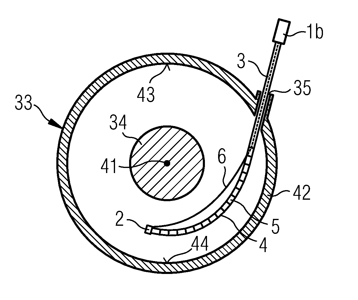
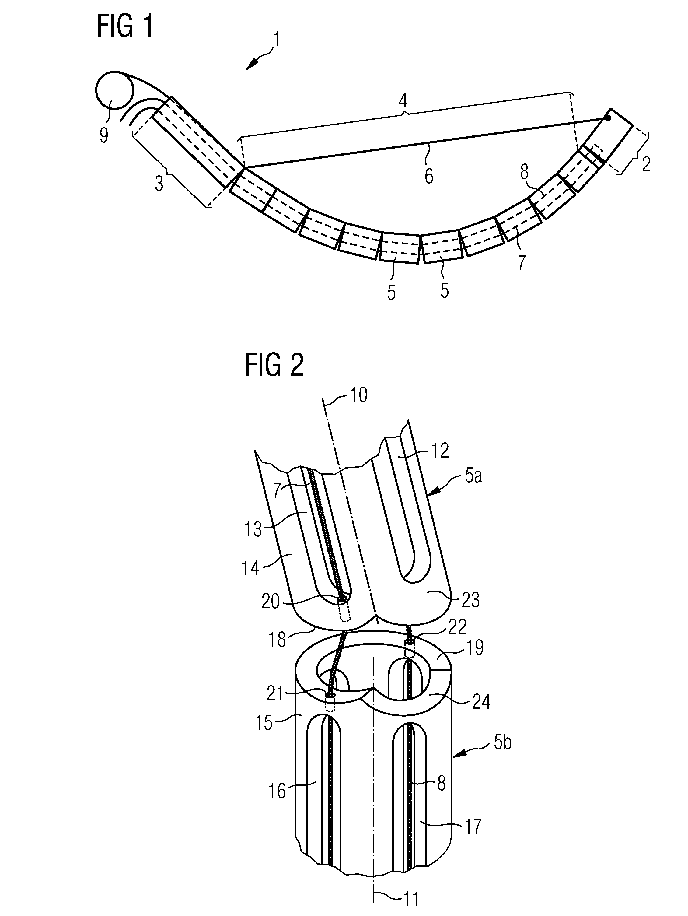
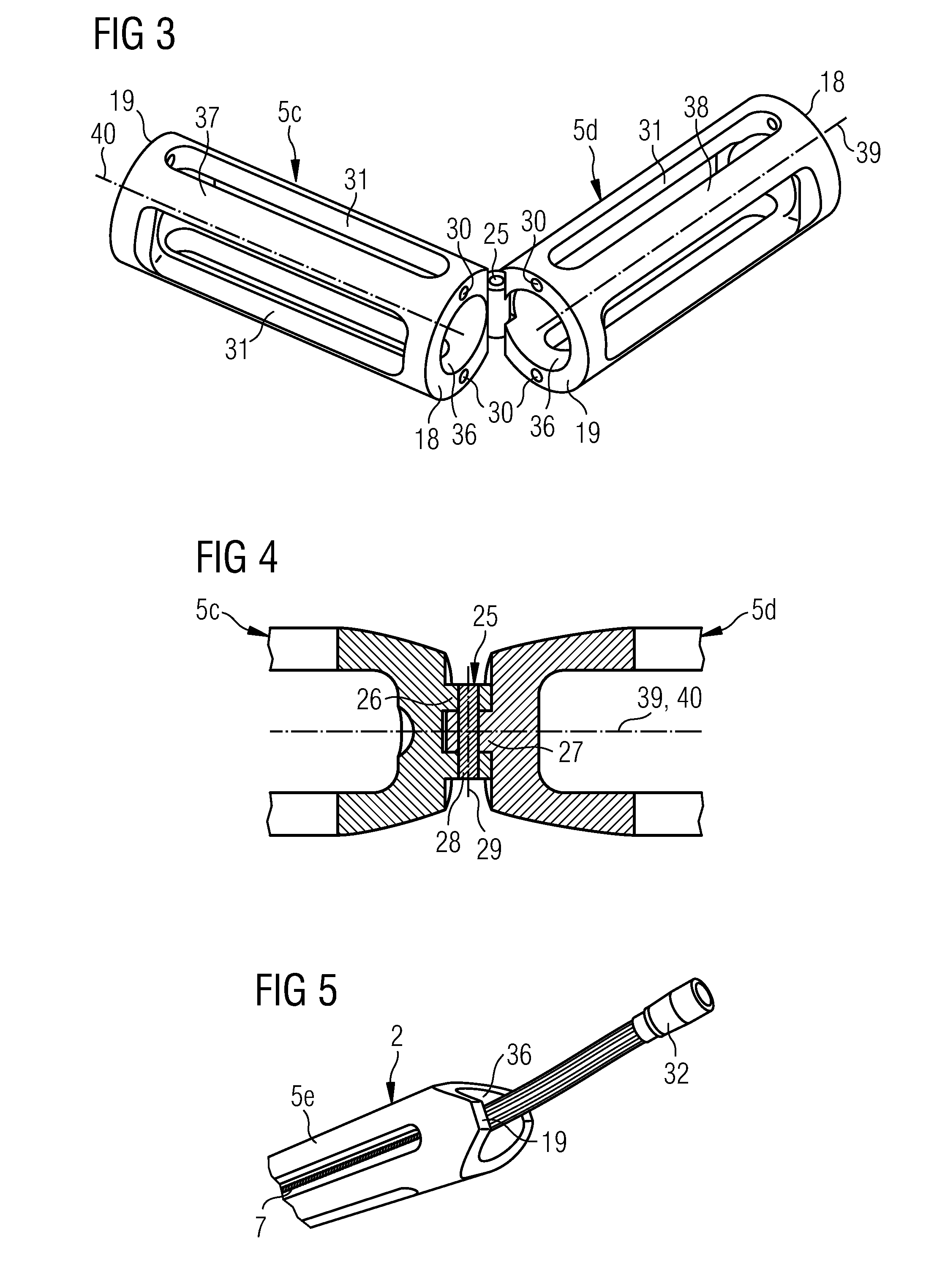
[0020]The inspection device according to the invention comprises a distal region, a proximal region and a flexible region disposed between the distal region and the proximal region. The flexible region comprises a number of segments that are movably disposed with respect to one another. At least one external guide element is disposed outside of the flexible region between the distal region and the proximal region such that the distal region can be moved with respect to the proximal region with the aid of the external guide element. The external guide element affords targeted maneuvering of the flexible region, particularly in narrow cavities. This also allows regions that are difficult to access to be reached with the aid of the inspection device according to the invention.
[0026]Moreover, at least one segment can have the shape of a hollow cylinder with a number of openings in the lateral face of the hollow cylinder. As a result of such an embodiment of the segments, it is possible to significantly reduce the weight of the inspection device without this being to the detriment of the stability of the inspection device.
[0039]With the aid of the inspection device according to the invention and the method according to the invention it is possible, in a quick and effective manner, to examine combustion chambers of gas turbines in particular in respect of possible faults. Since the inspection device according to the invention and the method according to the invention also afford the possibility of quickly and easily accessing and examining regions within the interior of the combustion chamber that are usually difficult to access, this significantly reduces the inspection time and hence the time that the gas turbine stands still. At the same time, this increases the availability and flexibility of the gas turbine or combustion chamber. In particular, it is quick and easy to find attacked or destroyed ceramic heat shields with the aid of the inspection device according to the invention and the method according to the invention.

Problems solved by technology

However, these inspection tools are frequently designed for a very specific application and, for example, are unsuitable for use in stationary gas turbines.
Inspecting annular combustion chambers typically provides particular difficulties as a result of the hub disposed centrally in the annular combustion chamber.
However, this link joint is only functional for as long as the counterpart of the one segment is mounted in the “socket” of the other segment.
If this is not the case, i.e. if the counterpart is not directly in the “socket”, then the desired movement in only one plane in particular, i.e. perpendicular to the rotational axis of the link joint, is no longer possible.
As a result of “separation” between individual segments, there may, inter alia, be rotation or torsion of these with respect to one another, as a result of which the aforementioned “end geometry” can no longer be obtained in a reliable and reproducible manner.
The frequency of this problem increases with the size and weight of the design of the individual segments.
Without further modifications, the inspection tool described in GB 2 425 764 B is unsuitable for inspecting stationary combustion chambers.
In particular, the aforementioned link joint is only able to ensure high positional accuracy to a limited extent because the individual segments are only interconnected by loose link joints.
The mutual contact between the segments can be lost at any time whenever the inspection tool is slack.
As a result of the large inaccuracies of the above-described inspection tool as a function of the size thereof, but also as a result of the illustrated problem of torsion as a result of the loose link joint between the individual segments, it is no longer possible to inspect large combustion chambers as are found in e.g. stationary gas turbines.

Method used


Image

  • Inspection device and method for positioning an inspection device
  • Inspection device and method for positioning an inspection device
  • Inspection device and method for positioning an inspection device

Examples


Embodiment Construction

[0053]FIG. 11 shows a longitudinal partial section of a gas turbine 100 in an exemplary manner.

[0054]In the interior, the gas turbine 100 has a rotor 103 with a shaft 101, which rotor is rotatably mounted around a rotational axis 102 and also referred to as turbine rotor.

[0055]An intake housing 104, a compressor 105, an e.g. toroidal combustion chamber 110, more particularly an annular combustion chamber, with a plurality of coaxially disposed burners 107, a turbine 108 and the exhaust-gas housing 109 successively follow one another along the rotor 103.

[0056]The annular combustion chamber 110 is in communication with an e.g. annular hot-gas duct 111. There, e.g. four turbine stages 112 connected in series form the turbine 108.

[0057]By way of example, each turbine stage 112 is made of two blade or vane rings. As seen in the flow direction of a work medium 113, a row 125 made of rotor blades 120 follows a guide-vane row 115 in the hot-gas duct 111.

[0058]Here, the guide vanes 130 are a...


PUM

PropertyMeasurementUnit
temperatureaaaaaaaaaa
flexibleaaaaaaaaaa
shapeaaaaaaaaaa

Abstract

An inspection device includes a distal area, a proximal area, and a flexible area disposed between the distal area and the proximal area. The flexible area includes a plurality of segments disposed displaceably to each other. At least one external guide element is disposed outside of the flexible area, between the distal area and the proximal area so that the distal area can be displaced with respect to the proximal area via the external guide element.

Description

CROSS REFERENCE TO RELATED APPLICATIONS[0001]This application is the US National Stage of International Application No. PCT / EP2010 / 067111, filed Nov. 9, 2010 and claims the benefit thereof. The International Application claims the benefits of European application No. 09014042.7 EP filed Nov. 10, 2009. All of the applications are incorporated by reference herein in their entirety.FIELD OF INVENTION[0002]The present invention relates to an inspection device and a method for positioning an inspection device. In particular, the invention relates to a borescope for use in stationary gas turbines.BACKGROUND OF INVENTION[0003]The patent literature has already described a multiplicity of inspection tools, for example endoscopes, bronchoscopes, borescopes and others. However, these inspection tools are frequently designed for a very specific application and, for example, are unsuitable for use in stationary gas turbines. Inspecting annular combustion chambers typically provides particular di...

Claims


Application Information

Patent Timeline
Patent Type & Authority Applications(United States)
IPC IPC(8): G01N37/00
CPCA61B1/0056A61B1/008F01D21/003G02B23/2476F23M11/04F23R2900/00019F05D2260/36
Inventor HANNOTT, KERSTINNEUHAUS, MARGARETESPEICHER, HARMWOSTMANN, KAI
Owner SIEMENS AG
Why Eureka
Try Eureka