Integrated heat management system in vehicle and heat management method using the same

a heat management system and heat management technology, applied in the direction of machines/engines, gearing details, transportation and packaging, etc., can solve the problems of inability to significantly contribute to the optimization of control temperature, the disadvantage of heat management system in terms of fuel-efficiency improvement, and the limitation of the implementation performance required, so as to shorten the engine warm-up time and prevent a bad effect

Active Publication Date: 2012-12-13
HYUNDAI MOTOR CO LTD
View PDF20 Cites 8 Cited by
  • Summary
  • Abstract
  • Description
  • Claims
  • Application Information

AI Technical Summary

Benefits of technology

[0014]Various aspects of the present invention are directed to providing an integrated heat management system in a vehicle, which is capable of shortening an engine warm-up time at the initial stage of engine start-up, preventing a bad effect in a low-temperature state due to a fast temperature increase of ATF, and optimizing heat management through integrated control for the engine and the automatic transmission, by changing an engine cooling water circulation flow in various manners between an engine and an automatic transmission, depending on an engine driving state, and a heat management method using the same.
[0015]Further, various aspects of the present invention are directed to providing an integrated heat management system which is capable of sufficiently satisfying performance required by a vehicle of which the fuel-efficiency is improved and the efficiency is increased in a high oil price environment, by significantly increasing heat management performance through integrated control of an engine and automatic transmission.
[0036]According to the exemplary embodiments of the present invention, the integrated heat management system and the heat management method may shorten the engine warm-up time by using engine heat generated at the initial stage of engine start-up without a loss, shorten the ATF warp-up time by using high-temperature engine cooling water, and optimize the heat management through the integrated control for the engine and the automatic transmission. Therefore, it is possible to significantly increase the fuel-efficiency of a vehicle having the integrated heat management system mounted thereon.
[0037]Further, according to the exemplary embodiments of the present invention, the integrated heat management system and the heat management method may prevent a durability reduction through the maximized cooling operation for the engine cooling water and the ATF using the integrated heat management for the engine and the automatic transmission. Through the prevention of the durability reduction, a maintenance cost and CO2 emission may be reduced.
[0038]Furthermore, according to the exemplary embodiments of the present invention, as the integrated heat management system is mounted in a vehicle, the fuel-efficiency and the efficiency may be significantly increased in accordance with a high oil price environment. Accordingly, it is possible to develop a vehicle which may achieve further improved fuel-efficiency.

Problems solved by technology

However, in the heat management system in which the engine and the automatic transmission are separately controlled, the temperature control of engine cooling water and the temperature control of automatic transmission fluid (ATF) are not considered together.
Accordingly, the heat management system may not significantly contribute to the control temperature optimization for the engine and the automatic transmission, of which the efficiencies significantly differ depending on the operation temperature.
Therefore, the above-described heat management system which is inadequate to perform the optimal temperature control has a limit in implementing performance required by a vehicle of which the fuel-efficiency is significantly improved and which is operated at high efficiency in accordance with the recent high oil price environment.
In particular, the heat management system is inevitably at a disadvantage in terms of the fuel-efficiency improvement which is the most important thing of all.

Method used


Image

  • Integrated heat management system in vehicle and heat management method using the same
  • Integrated heat management system in vehicle and heat management method using the same
  • Integrated heat management system in vehicle and heat management method using the same

Examples


Embodiment Construction

[0046]Reference will now be made in detail to various embodiments of the present invention(s), examples of which are illustrated in the accompanying drawings and described below. While the invention(s) will be described in conjunction with exemplary embodiments, it will be understood that present description is not intended to limit the invention(s) to those exemplary embodiments. On the contrary, the invention(s) is / are intended to cover not only the exemplary embodiments, but also various alternatives, modifications, equivalents and other embodiments, which may be included within the spirit and scope of the invention as defined by the appended claims.

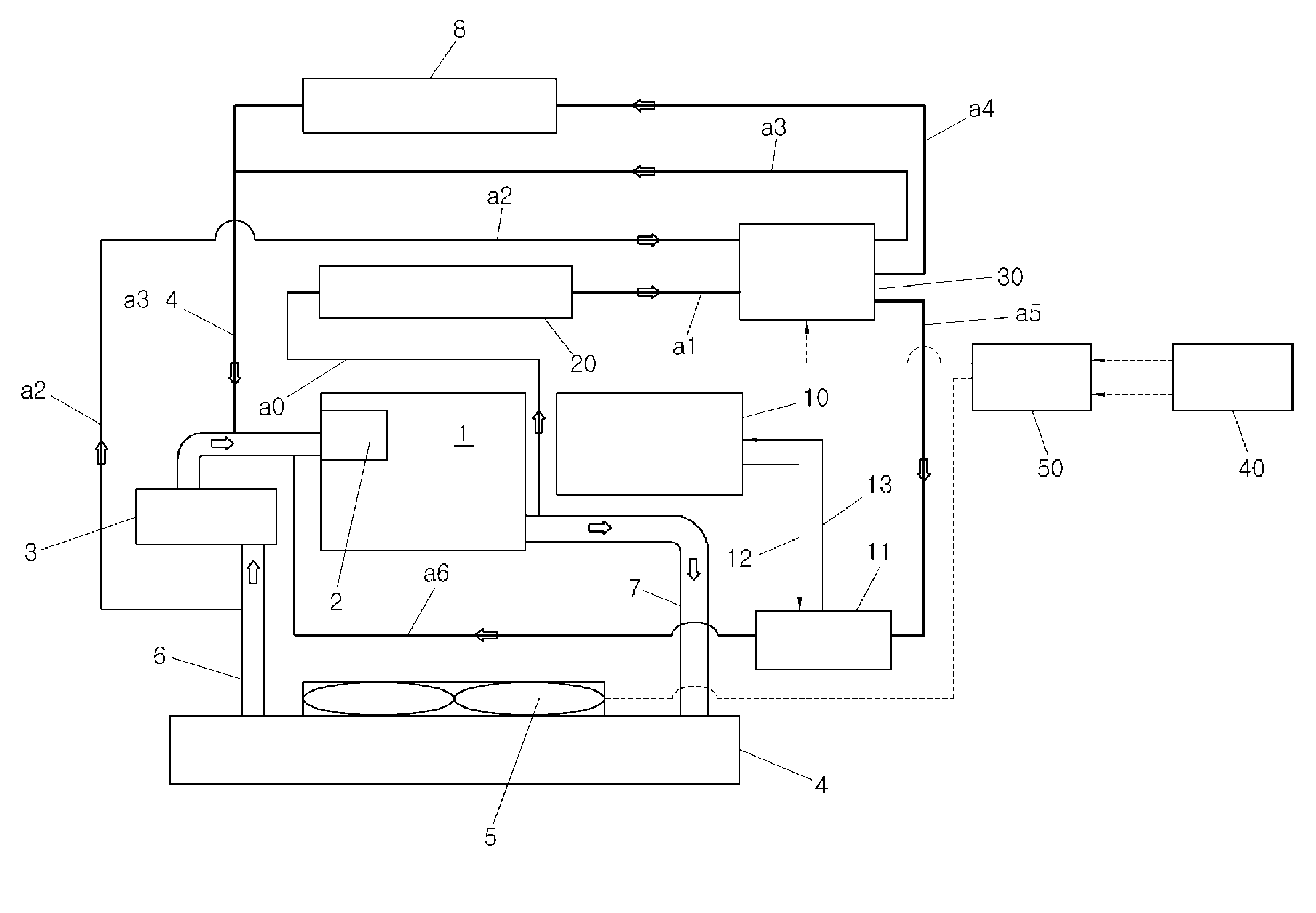
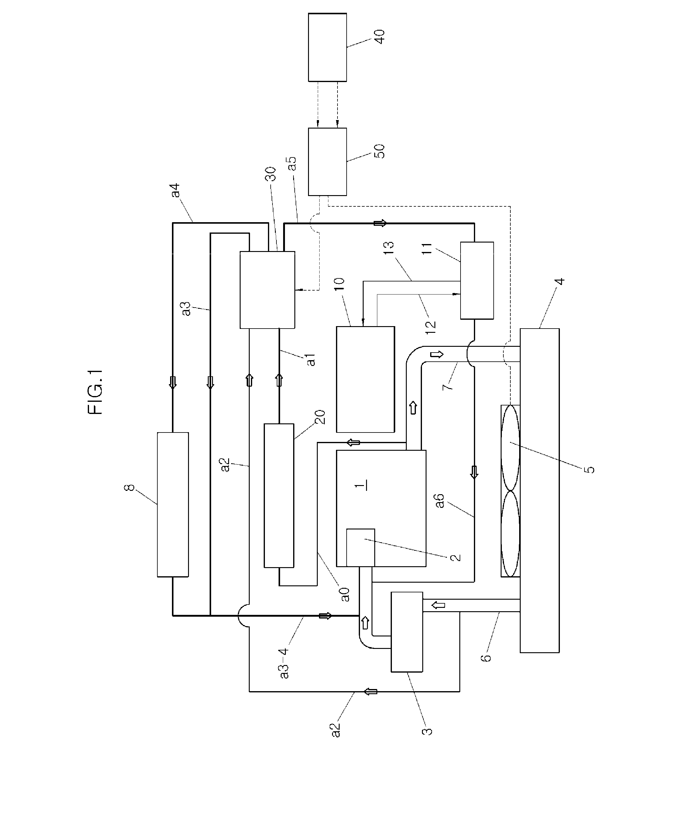
[0047]FIG. 1 illustrates the structure of an integrated heat management system in a vehicle according to an exemplary embodiment of the present invention.

[0048]Referring to FIG. 1, the integrated heat management system includes an engine system, a transmission system, an exhaust heat recovery system 20, a circulation flow system, and ...


PUM


Abstract

An integrated heat management system may include an engine system circulation line around an engine and a transmission circulation line around an automatic transmission. The engine system circulation line and the transmission circulation line may be integrated by a control valve having a plurality of input and output ports. The integrated heat management system controls opening and closing of the control valve in accordance with engine cooling water temperature and automatic transmission fluid (ATF) temperature, which may be changed after engine start-up, and implements a variety of modes for varying an engine cooling water flow. Therefore, the integrated heat manage system shortens an engine warm-up time, prevents a bad effect in a low-temperature state due to a fast temperature increase of the ATF, and satisfies performance required by a vehicle of which the fuel-efficiency may be improved and the efficiency may be increased in a high oil price environment.

Description

CROSS-REFERENCE TO RELATED APPLICATIONS[0001]The present application claims priority to Korean Patent Application Number 10-2011-0055626 filed Jun. 9, 2011, the entire contents of which application is incorporated herein for all purposes by this reference.BACKGROUND OF THE INVENTION[0002]1. Field of the Invention[0003]The present invention relates to an integrated heat management system in a vehicle, and more particularly, to an integrated heat management system in a vehicle, which is capable of performing integrated heat management for an engine and an automatic transmission and a heat management method using the same[0004]2. Description of Related Art[0005]In general, a heat management system applied to a vehicle is operated in such a manner as to individually control an engine and an automatic transmission in a state in which the engine and the automatic transmission are separated from each other.[0006]FIG. 10 illustrates a general heat management system including an engine and a...

Claims


Application Information

Patent Timeline
Patent Type & Authority Applications(United States)
IPC IPC(8): B60H1/00
CPCF01P2060/16F01P7/14F01P2037/02F01P2060/045F01P7/165F16H57/0413F01P2060/08B60W10/30B60K11/00B60W40/12
Inventor KIM, DAEKWANG
Owner HYUNDAI MOTOR CO LTD
Why Eureka
Try Eureka