Object detecting apparatus and object detecting method

Active Publication Date: 2012-12-13
TOYOTA JIDOSHA KK
View PDF1 Cites 19 Cited by
  • Summary
  • Abstract
  • Description
  • Claims
  • Application Information

AI Technical Summary

Benefits of technology

[0035]According to the present invention, it is possible to further improve the detection accuracy of the lateral position of the target in the object detecting apparatus for

Problems solved by technology

However, it is difficult to correctly acquire the edge of the target by means of the radar.
However, when the stereo image sensor is used as the image sensor, it is necessary to

Method used


Image

  • Object detecting apparatus and object detecting method
  • Object detecting apparatus and object detecting method
  • Object detecting apparatus and object detecting method

Examples


first embodiment

[0051]A first embodiment of the present invention will be explained on the basis of FIGS. 1 to 9.

(Schematic Arrangement)

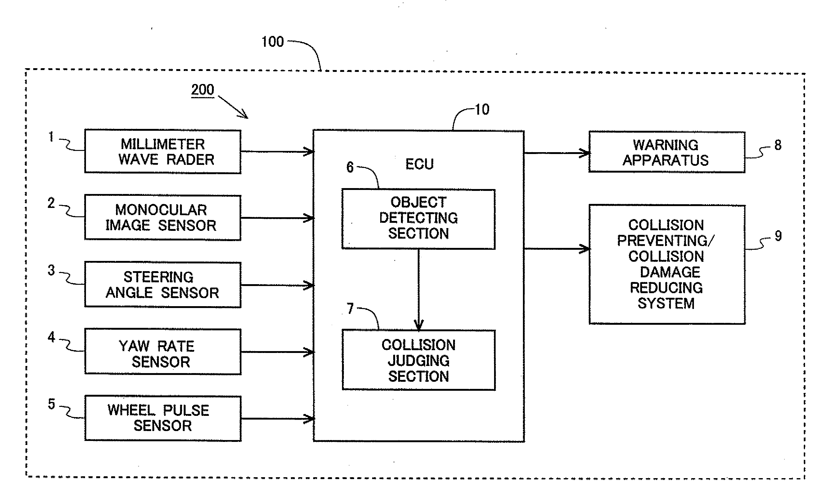
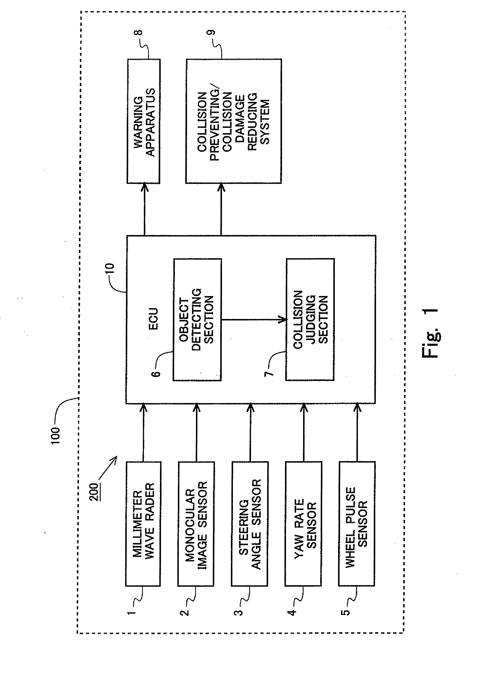
[0052]In this section, an explanation will be made about a case in which the present invention is applied to a collision predicting apparatus. FIGS. 1 and 2 show block diagrams illustrating a schematic arrangement of the collision predicting apparatus according to this embodiment. The collision predicting apparatus 200 is carried on a vehicle 100, which is an apparatus to predict the collision between a subject vehicle 100 and an obstacle including, for example, another vehicle (object vehicle) and a pedestrian or walker. A warning apparatus 8 and a collision preventing / collision damage reducing system 9, which are operated if the collision with the obstacle is predicted, are carried on the vehicle 100 in addition to the collision predicting apparatus 200.

[0053]The collision predicting apparatus 200 comprises a millimeter wave radar 1, a monocular image sensor 2, a...

second embodiment

[0095]A first embodiment of the present invention will be explained on the basis of FIGS. 10 to 14. In this section, an explanation will be made about only the points or features different from those of the first embodiment.

(Schematic Arrangement)

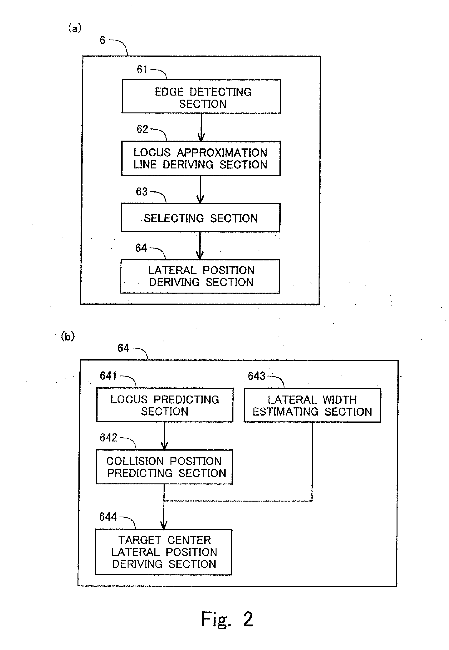
[0096]FIG. 10 shows a block diagram illustrating a schematic arrangement of an object detecting section 6 according to this embodiment. As shown in FIG. 10, the object detecting section 6 according to this embodiment includes a weight applying section 65 and a reliability total value calculating section 66 in addition to the edge detecting section 61, the locus approximation line deriving section 62, the selecting section 63, and the lateral position deriving section 64. Details of the weight applying section 65 and the reliability total value calculating section 66 will be described later on.

(Method for Deriving Lateral Position)

[0097]A method for deriving the lateral position of an obstacle according to this embodiment will be explained o...


PUM


Abstract

An object of the present invention is to further improve the detection accuracy of a lateral position of a target in an object detecting apparatus for detecting an object by using a radar and a monocular image sensor. In the present invention, a target corresponding to a target recognized by the radar is extracted and a right edge and a left edge of the target are acquired from an image picked up by the monocular image sensor. Further, locus approximation lines, which are straight lines or predetermined curved lines for approximating loci of the right edge and the left edge, are derived for the both edges. The edge, which has a larger number of edges existing on the locus approximation line, is selected as a true edge of the target from the right edge and the left edge. The lateral position of the target is derived on the basis of the position of the selected edge.

Description

TECHNICAL FIELD[0001]The present invention relates to an object detecting apparatus and an object detecting method in which an object is detected on the basis of information acquired by a radar and an image sensor.BACKGROUND ART[0002]In recent years, safety systems such as PCS (Pre-crash safety system) and the like are developed in order to avoid the collision or reduce the damage caused by the collision. In order to preferably realize such a safety system, it is necessary to correctly grasp, for example, the position and the size of an obstacle including, for example, a pedestrian and a vehicle other than a subject vehicle as well as the distance between the obstacle and the subject vehicle. An object detecting apparatus, which is based on the use of a radar and a stereo image sensor, is known as a technique for grasping, for example, the position, the size, and the distance as described above.[0003]When the radar is used, it is possible to recognize a target (object provided as a ...

Claims


Application Information

Patent Timeline
IPC IPC(8): G01S13/93G01S13/931
CPCB60R21/013B60R21/0134G01S13/931G01S2013/9375G01S13/867G01S2013/9353G08G1/16G08G1/166G01S2013/932G01S2013/93271
Inventor KATOH, MASAYUKI
Owner TOYOTA JIDOSHA KK
Why Eureka
Try Eureka