Vehicle optical sensor system

a technology of optical sensor and vehicle, which is applied in the field of vehicle optical sensor system, can solve the problems of reducing the frame rate of images, preventing optimum performance, and affecting the performance of the image,

Inactive Publication Date: 2012-12-13
DELPHI TECH INC
View PDF4 Cites 17 Cited by
  • Summary
  • Abstract
  • Description
  • Claims
  • Application Information

AI Technical Summary

Problems solved by technology

Unfortunately, performance tradeoffs exist when using a single optical sensor system due to light sensitivity, spectrum sensitivity, and field of view requirements specific to each vehicle warning and control system.
These performance tradeoffs have previously precluded optimum performance for every vehicle warning and control system.
However, a larger pixel size requires a larger optoelectronic device for equivalent pixel resolution.
However, longer exposure time will decrease the frame rate of the images.
However, a larger aperture usually requires a larger lens, which increases the packaging size of the optical sensor system.
There are performance tradeoffs that may be required if a single optical sensor system is used with all three of these vehicle warning and control systems.
Again, using a single optical sensor system may require performance tradeoffs.

Method used


Image

  • Vehicle optical sensor system
  • Vehicle optical sensor system
  • Vehicle optical sensor system

Examples


Embodiment Construction

[0021]While the specification concludes with claims defining the features of the invention that are regarded as novel, it is believed that the invention will be better understood from a consideration of the following description in conjunction with the drawing figures, in which like reference numerals are carried forward.

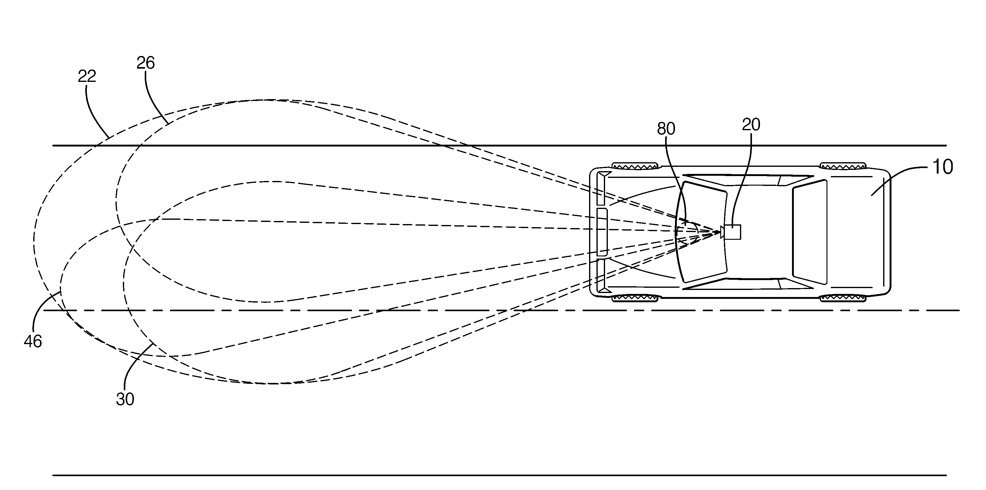
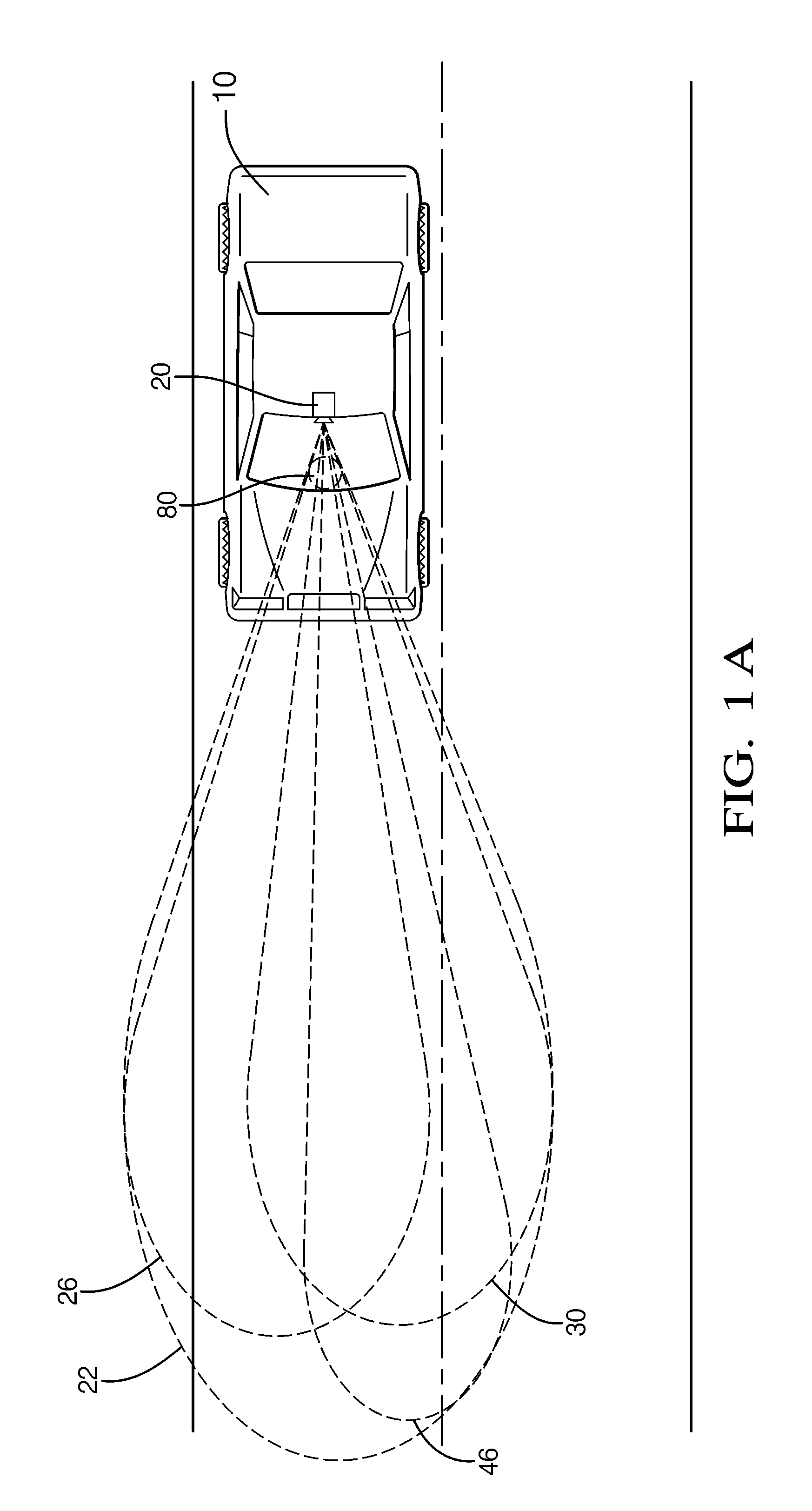
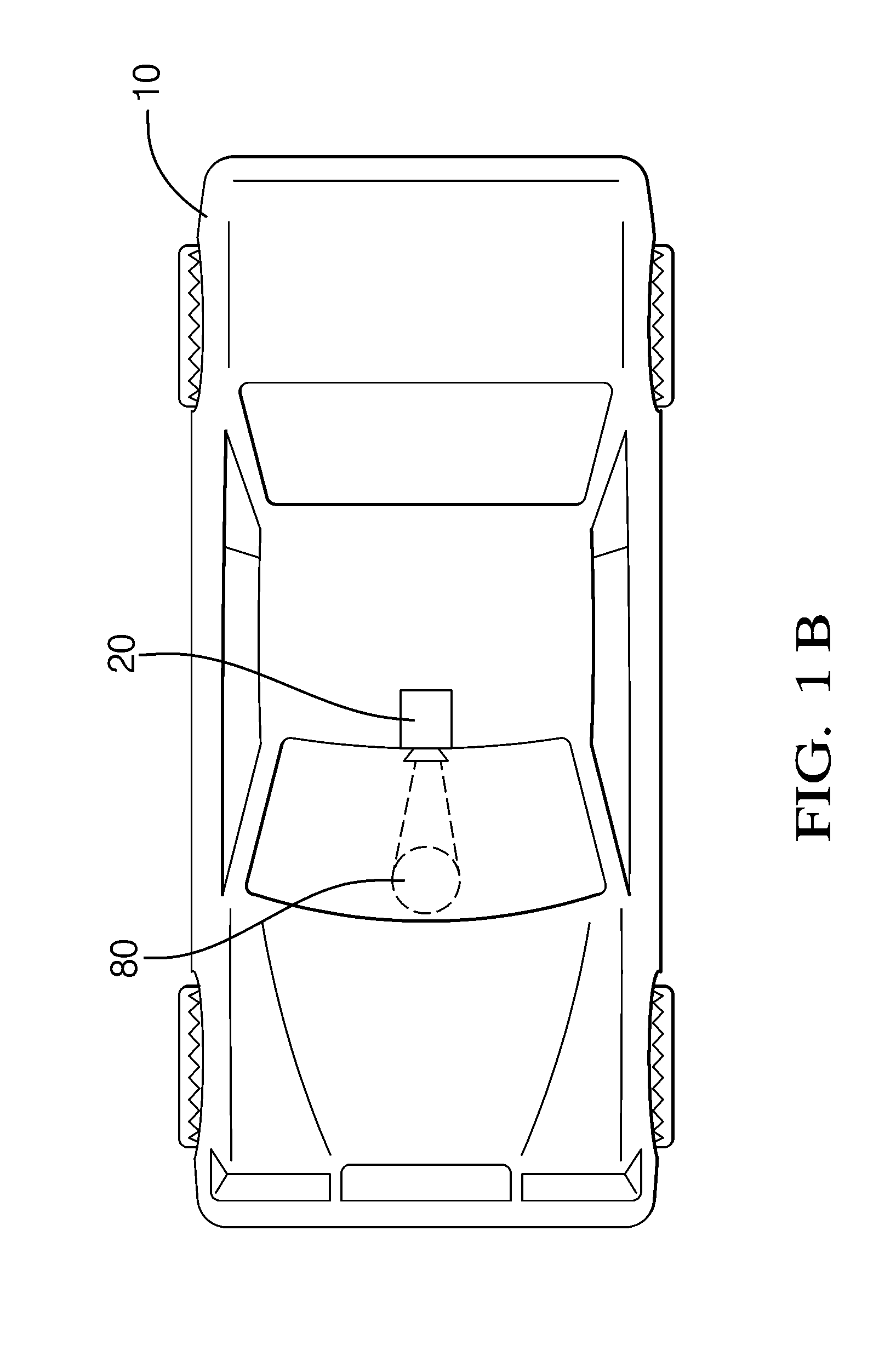
[0022]Developments in complementary metal oxide semiconductor optoelectronic device manufacturing technology have led to the creation of optoelectronic devices that offer significant size and cost advantages over optoelectronic devices used previously with automotive optical sensor systems. This manufacturing technology allows an optoelectronic device to be made at the semiconductor wafer die level, herein referred to as optoelectric dies. These optoelectronic dies are commonly used in wafer level cameras. Wafer level cameras are approximately one third the size of optical sensors used previously in automotive applications.

[0023]Because a wafer level camera enjoys a...


PUM


Abstract

An optical sensor system adapted for use on a vehicle including a plurality of optoelectronic devices and a single high efficiency first lens. The optical sensor system is positioned on the vehicle to view a field of view about the vehicle. The optical sensor system may provide multiple independent video signals to multiple vehicle warning and control systems. Each video signal that is generated by each optoelectronic device may be optimized for a specific vehicle warning or control system by using additional second lenses to change the field of view, optical filters to change the spectral sensitivity, and / or independent exposure times to change the light sensitivity or dynamic range. The optoelectronic devices may be optoelectronic dies or cores, such as those used in wafer level cameras.

Description

TECHNICAL FIELD OF INVENTION[0001]The invention generally relates to a vehicle optical sensor system, and more particularly relates to an optical sensor system with multiple optoelectronic devices receiving images through a common lens.BACKGROUND OF INVENTION[0002]Optical sensor systems are frequently used in automobiles and other vehicles to provide images of areas around the vehicle. In some instances, these images are used by various vehicle warning and control systems. In the example of forward looking optical sensor systems, the images provided by the sensor may be used as inputs for collision avoidance, lane departure detection, forward collision warning, side warning, adaptive cruise control, night vision, headlight control, rain sensing systems and others. Typically, a forward looking optical sensor system is located behind the windshield near the rear view mirror to obtain a view of the road ahead which is similar to the driver's view. Optical sensor systems may also be use...

Claims


Application Information

Patent Timeline
Patent Type & Authority Applications(United States)
IPC IPC(8): H04N7/18
CPCG01B11/24
Inventor TAYLOR, RONALD M.
Owner DELPHI TECH INC
Why Eureka
Try Eureka