Performing Stuck-At Testing Using Multiple Isolation Circuits
- Summary
- Abstract
- Description
- Claims
- Application Information
AI Technical Summary
Benefits of technology
Problems solved by technology
Method used
Image
Examples
Embodiment Construction
FIG. 1—Exemplary Integrated Circuit
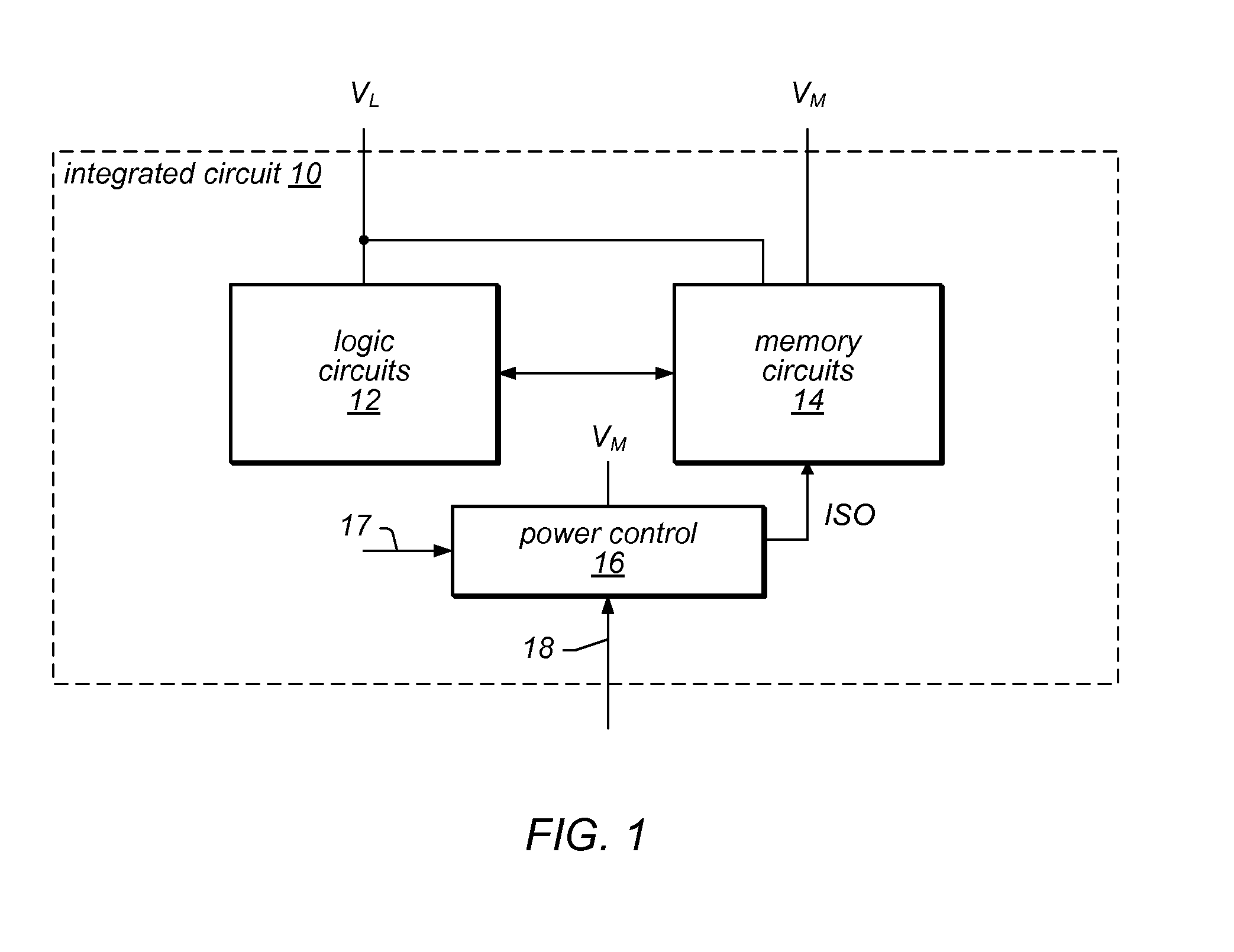
[0021]Turning now to FIG. 1, a block diagram of one embodiment of an integrated circuit 10 is shown. In the illustrated embodiment, the integrated circuit includes logic circuits 12, memory circuits 14, and a power control circuit 16. The logic circuits 12 are coupled to the memory circuits 14. The power control circuit 16 is coupled to the memory circuits 14 (specifically, via a ISO signal). The logic circuits 12 are powered by a first supply voltage provided to the integrated circuit 10 (labeled VL in FIG. 1). The memory circuits 14 and the power control circuit 16 are powered by a second power supply voltage provided to the integrated circuit 10 (labeled VM in FIG. 1). In the illustrated embodiment, the memory circuits 14 are also powered by the VL supply voltage, as will be explained in more detail for certain embodiments below. The integrated circuit 10 may generally comprise the logic circuits 12, the memory circuits 14, and the power control...
PUM
 Abstract
Description
Claims
Application Information
 - R&D
- Intellectual Property
- Life Sciences
- Materials
- Tech Scout
- Unparalleled Data Quality
- Higher Quality Content
- 60% Fewer Hallucinations
Browse by: Latest US Patents, China's latest patents, Technical Efficacy Thesaurus, Application Domain, Technology Topic, Popular Technical Reports.
© 2025 PatSnap. All rights reserved.Legal|Privacy policy|Modern Slavery Act Transparency Statement|Sitemap|About US| Contact US: help@patsnap.com


