Aseptic packaging installation having aseptic buffer zones

a technology of aseptic packaging and buffer zones, which is applied in the direction of packaging machines, bottle-handling machines, bottle operations, etc., can solve the problems of complex installation, difficult implementation of dynamic sealing, and high production, maintenance and upkeep costs, so as to reduce pollution risk and simplify production and maintenance.

Inactive Publication Date: 2012-12-20
SERAC GROUP
View PDF9 Cites 7 Cited by
  • Summary
  • Abstract
  • Description
  • Claims
  • Application Information

AI Technical Summary

Benefits of technology

[0005]An object of the invention is to provide an aseptic packaging installation that minimizes the risk of pollution inside the packaging zone, while being simpler to make and maintain.SUMMARY OF THE INVENTION
[0007]Thus, two zones are defined inside the enclosure, namely: a packaging zone in which the containers are treated (the treatment may for example be filling and / or closing the containers), and a buffer zone in which the aseptic constraints are less severe than those relating to the packaging zone so that the presence of dynamic sealing elements in the buffer zone is less problematic. In addition, it has been observed that the efficiency of the sterile laminar stream for maintaining aseptic conditions is best when it exits in uniform manner, with a minimum of disturbance.
[0009]This makes it possible to limit as much as possible the presence in the packaging zone of elements having outside surfaces that can collect germs and that must be cleaned.
[0012]The tray thus recovers waste water from the enclosure while being outside of the packaging zone, and that facilitates the design of the installation and maintenance operations.

Problems solved by technology

In contrast, installations having carousels and / or rotating platforms, dedicated to filling bottles and other containers of that type, present various constraints, in particular relating to movement of the containers due to the fact that the containers are individual and independent from one another.
Implementing said dynamic sealing is made difficult by being positioned inside the aseptic zone.
That complicates production, upkeep, and maintenance of the installation.

Method used


Image

  • Aseptic packaging installation having aseptic buffer zones
  • Aseptic packaging installation having aseptic buffer zones

Examples


Embodiment Construction

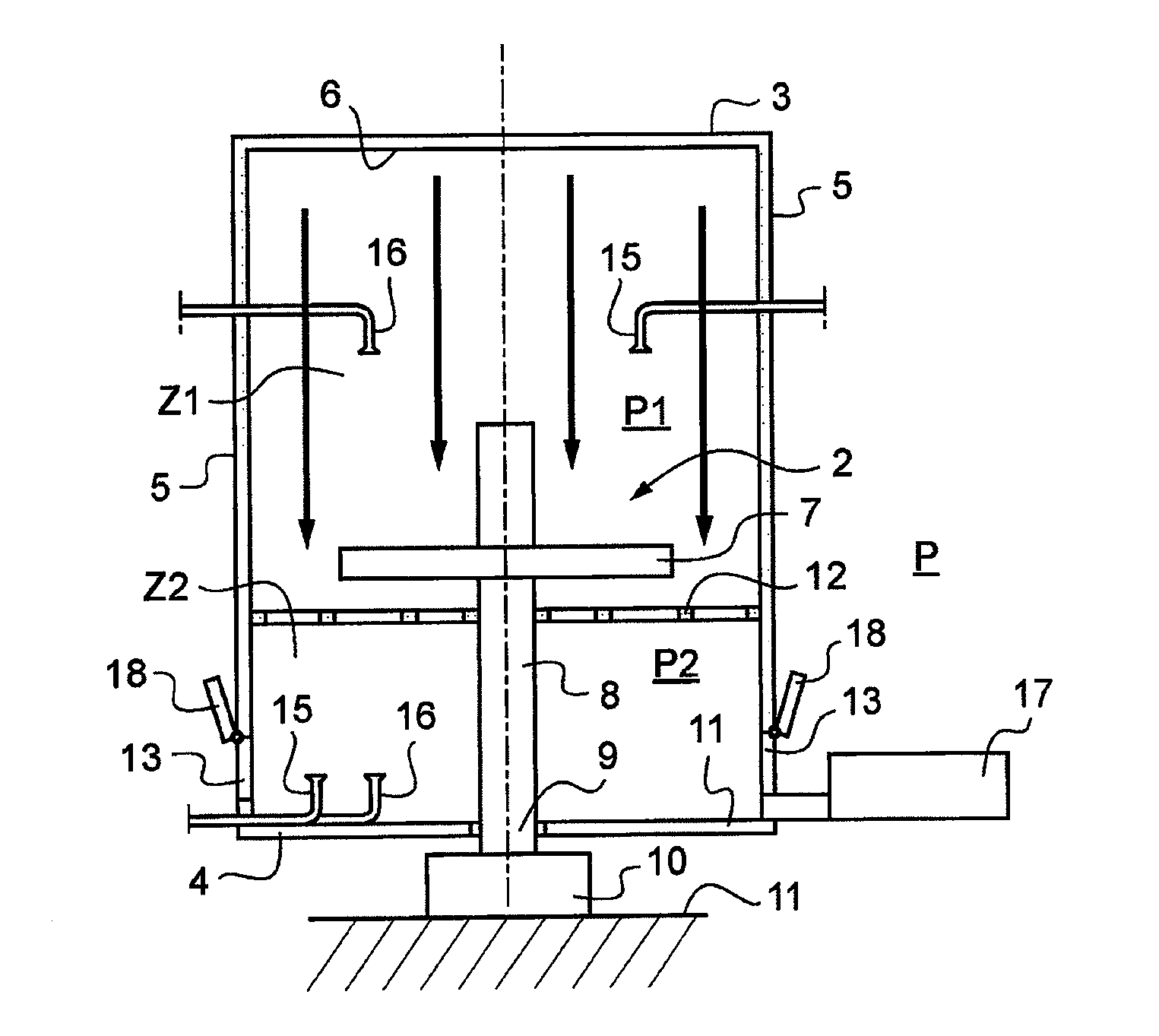
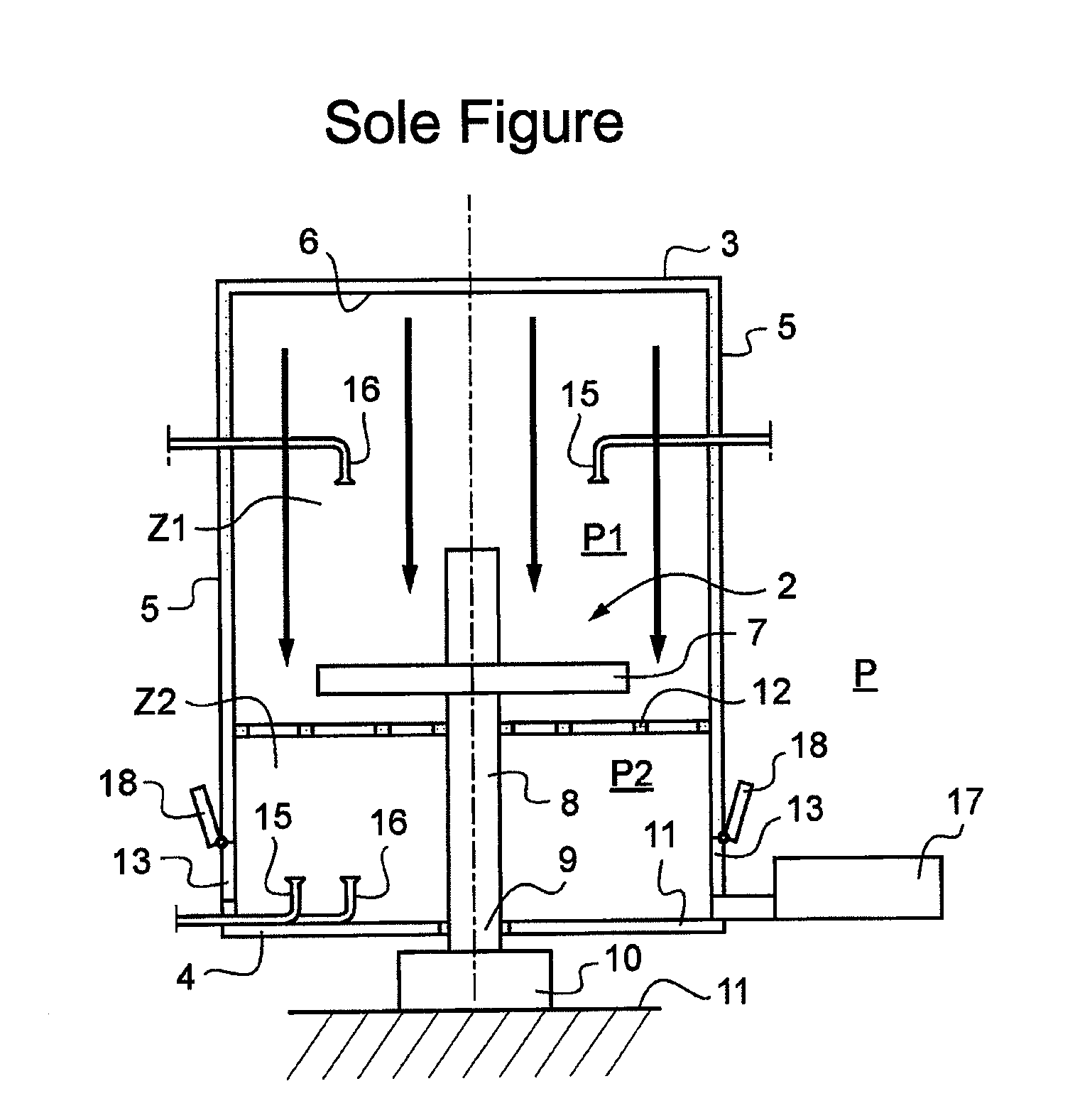
[0015]With reference to the figure, the aseptic packaging installation shown is designed for packaging a substance in containers (not shown). The installation includes a stand 1 carrying a line of machines 2 (only one of which is shown in the figure), such as filler machines, cap heat-sealing machines, and stopper insertion machines, and an enclosure 3 surrounding the machines and comprising a floor 4, walls 5, and a ceiling 6.

[0016]Each machine 2 includes a platform 7, provided with container treatment means, which is constrained to rotate with a column 8 mounted to rotate on the stand 1. A stationary table 11 extends under the platform 7 in a position that is spaced apart therefrom and that has the column 8 passing therethrough. Under the table 11, the column 8 has a portion 9 for connection to rotary drive means 10.

[0017]The platform 7 of each machine 2 extends into a packaging zone Z1 that is defined inside the enclosure 3 and that is subjected to a sterile laminar stream (repre...


PUM


Abstract

An aseptic packaging installation in individual containers, comprising a stand on which there is mounted an enclosure (3) that has a floor (4) with an overhead ceiling (6) and that receives at least one rotatable platform (7) in a packaging zone (Z1) subjected to a sterile laminar stream flowing vertically from the ceiling of the packaging zone at a rate that is adapted to establish in the packaging zone a first pressure (P1) that is greater than the surrounding pressure, the installation being characterized in that the enclosure is provided with laminar stream exhaust means for removing the laminar stream from the packaging zone via a buffer zone extending between the packaging zone and the floor.

Description

BACKGROUND OF THE INVENTION[0001]It is known that in order to ensure long-term preservation of foodstuffs without subjecting them to particular refrigeration conditions, it is necessary for the foodstuffs to be packaged in aseptic manner, i.e. without germs being introduced into the container during the various stages of packaging. So as to ensure packaging is aseptic, it is known in particular that it is necessary to subject the line of machines performing packaging to a sterile environment that is generally obtained by causing a laminar filtered stream of air to flow vertically over the line of machines.[0002]To this end, existing aseptic packaging installations, as described in particular in document FR-A-2 800 710, comprise a cabin forming around the line of machines a packaging zone presenting a high degree of asepsis, at least one side of the packaging zone being beside an operator zone that is maintained at a lower degree of asepsis than the packaging zone proper by providing...

Claims


Application Information

Patent Timeline
Patent Type & Authority Applications(United States)
IPC IPC(8): B65B55/02
CPCB67C7/0073B65B55/027
Inventor GUEGUEN, DELPHINE
Owner SERAC GROUP
Why Eureka
Try Eureka