Vibration determination method and vibration determination device

a vibration determination and vibration technology, applied in the direction of vibration measurement in solids, manufacturing tools, instruments, etc., can solve the problems of poor determination accuracy between “forced chatter vibration” and “regenerative chatter vibration” in the machining condition described above, and the so-called chatter vibration may possibly occur, etc., to achieve the effect of precise natural vibration type vibration determination range, accurate determination and easy grasp

Active Publication Date: 2012-12-20
OKUMA CORP
View PDF14 Cites 13 Cited by
  • Summary
  • Abstract
  • Description
  • Claims
  • Application Information

AI Technical Summary

Benefits of technology

[0015]Further, according to the third aspect of the present invention in particular, an interval between frequencies taking the peak values is obtained, and the natural vibration type vibration determination range is obtained after exclusion of peak values at which the interval between frequencies becomes the rotation frequency and/or the flute-passage frequency or becomes an integral multiple thereof out of the peak values from an object of determination. Therefore more precise natural vibration type vibration determination range can be obtained, and more

Problems solved by technology

In a machine tool performing machining by rotating a rotary shaft, so-called chatter vibration may possibly occur during machining due to improper machining conditions such as depth of cut and rotation speed of the rotary shaft, and the like.
When the chatter vibration occurs, finishing accuracy of the machined surface may be reduced and the tool may be broken.
Therefore, when the chatter vibration is determined using only the maximum value in the frequency-domain vibrational acceleration as described in Japanese Unexamined Patent Application Publicatio

Method used


Image

  • Vibration determination method and vibration determination device
  • Vibration determination method and vibration determination device
  • Vibration determination method and vibration determination device

Examples


Embodiment Construction

[0024]A vibration determination method and a vibration determination device according to an embodiment of the present invention will be described in detail below based on the drawings.

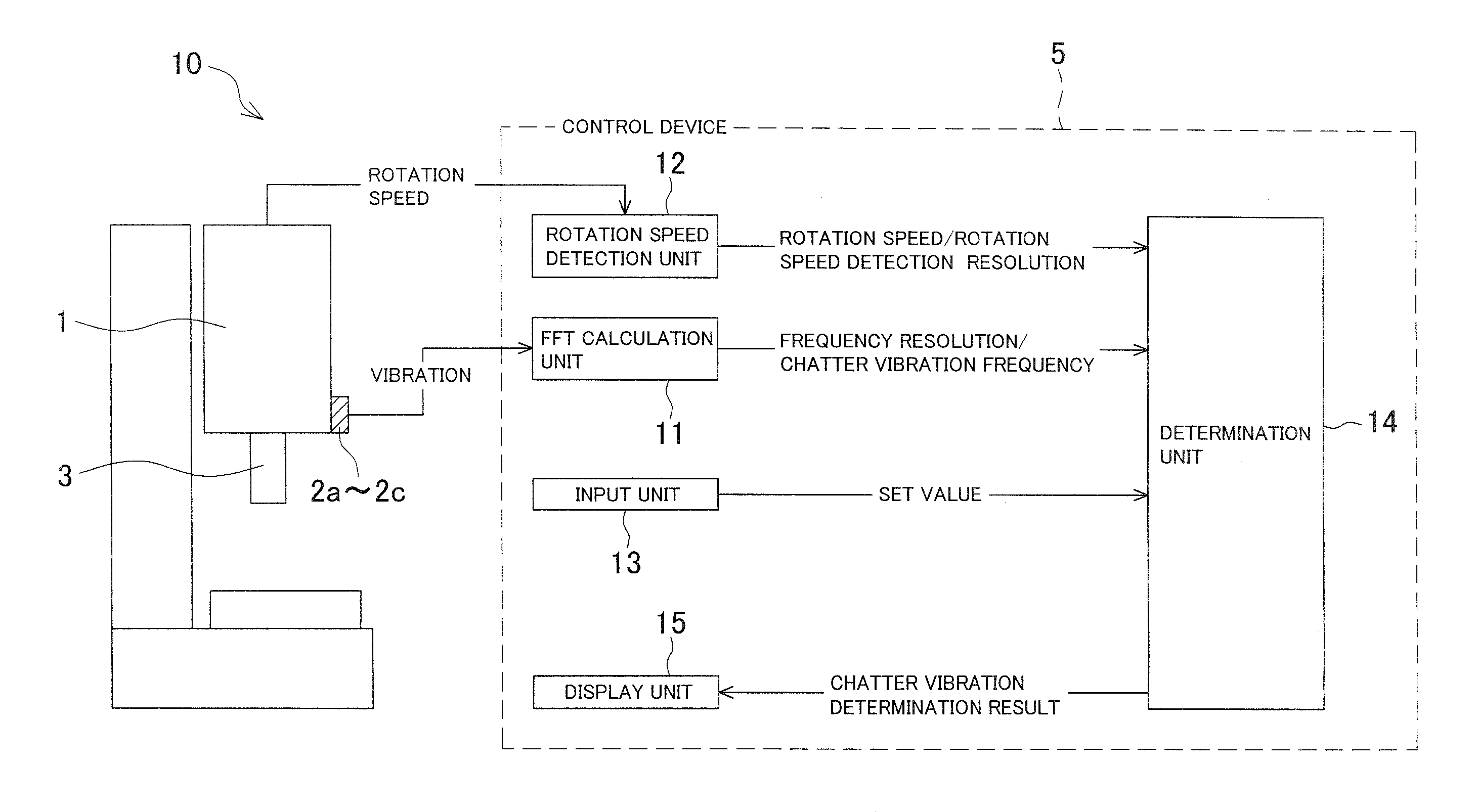
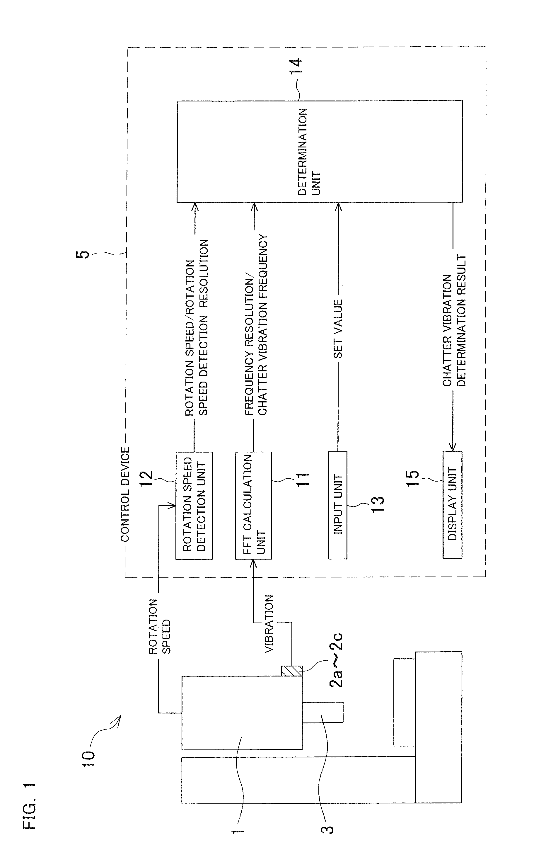
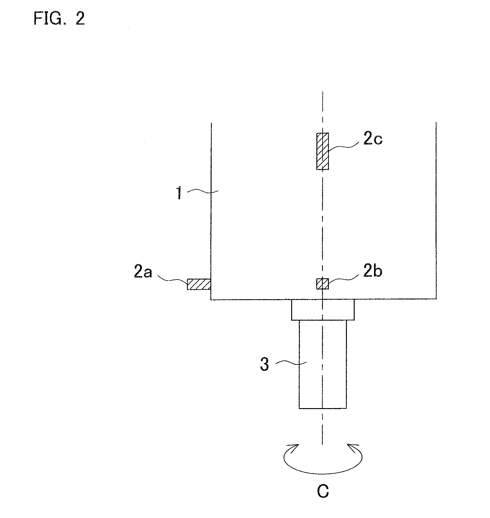
[0025]FIG. 1 is an explanatory drawing showing a block configuration of a vibration determination device 10. FIG. 2 is an explanatory drawing showing a rotary shaft housing 1 becoming an object of monitoring the vibration as seen from a side, and FIG. 3 is an explanatory drawing showing the rotary shaft housing 1 as seen from the axial direction.

[0026]The vibration determination device 10 determines a type of chatter vibration occurring in a rotary shaft 3 provided in the rotary shaft housing 1 so as to be rotatable around an axis C. The vibration determination device 10 includes vibration sensors 2a to 2c and a control device 5. The vibration sensors 2a to 2c detect time-domain vibrational acceleration (which means the vibrational acceleration on the time axis), which is a characteristic value accompa...


PUM


Abstract

Determination of chatter vibration is done for a plurality of peak values that appears when frequency-domain vibrational acceleration is obtained through fast Fourier analysis on time-domain vibrational acceleration. In machining at a low rotation speed and machining using a tool with small flute number in particular, a type of chatter vibration that has occurred can be accurately determined, and “natural vibration type forced chatter vibration” occurring due to friction between a tool and a workpiece and an impact force caused by machining can also be determined.

Description

BACKGROUND OF INVENTION[0001]This application claims the benefit of Japanese Patent Application Number 2011-134382 filed on Jun. 16, 2011, the entirety of which is incorporated by reference.TECHNICAL FIELD[0002]The present invention relates to a vibration determination method for determining the type of chatter vibration occurring in a machine tool during machining performed by rotating a tool or a workpiece during machining, and a vibration determination device for executing the vibration determination method.BACKGROUND ART[0003]In a machine tool performing machining by rotating a rotary shaft, so-called chatter vibration may possibly occur during machining due to improper machining conditions such as depth of cut and rotation speed of the rotary shaft, and the like. When the chatter vibration occurs, finishing accuracy of the machined surface may be reduced and the tool may be broken. Therefore, suppression of the chatter vibration is required.[0004]There are two types of chatter ...

Claims


Application Information

Patent Timeline
IPC IPC(8): G01H13/00
CPCB23Q17/0976
Inventor TANAKA, TAKAAKI
Owner OKUMA CORP
Why Eureka
Try Eureka