Solar air thermal energy system and energy purchase agreement method

a solar energy and thermal energy technology, applied in the field of solar energy, can solve the problems of complex retrofit construction, increased cost of fossil fuels and/or electricity to heat buildings, and lack of financial structur

Inactive Publication Date: 2012-12-20
REVOLUTION ENERGY
View PDF5 Cites 3 Cited by
  • Summary
  • Abstract
  • Description
  • Claims
  • Application Information

AI Technical Summary

Problems solved by technology

The price of using fossil fuels and/or electricity to heat buildings has been increasing, is expected to increase and has negative environmental consequences.
Other technologies, such as geothermal provide additional methods for stabilized thermal needs but rely on electricity to drive the system and complicated retrofit construction.
Active solar, through hot water collectors and hot air collectors can also lower heat loads, but all of these options are often not selected due to their higher upfront costs.
However, such a method only discusses solar hot water, and specifically that the rate charged is not

Method used


Image

  • Solar air thermal energy system and energy purchase agreement method
  • Solar air thermal energy system and energy purchase agreement method
  • Solar air thermal energy system and energy purchase agreement method

Examples


third embodiment

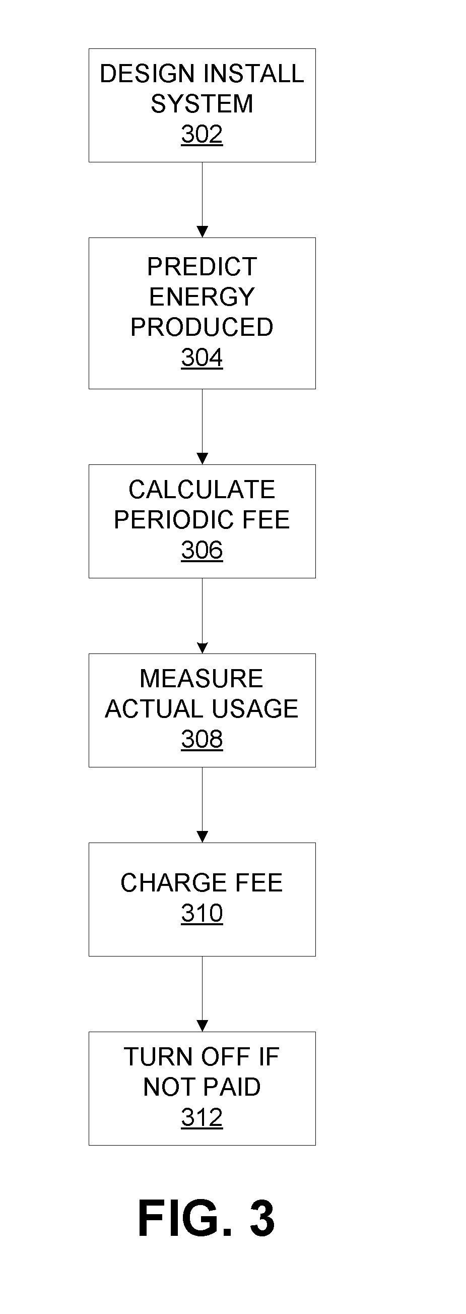
[0016]Reference will be made in detail to embodiments of a system and method that satisfies the need for financing the system cost and the installation of a solar hot air system and charging a periodic fee based on the energy output of the system or the energy displaced by the system from the existing building system. A first exemplary embodiment of a system according to the present invention includes perforated solar hot air collector panels, spacing dips, extruded vertical bars, duct work to connect to a ventilation system, decorative capping, sensors to determine air flow and temperature, calculating means for determining a periodic fee amount of energy produced, and means for turning off the system in the event fees are not paid. A method according the present invention may include the steps of designing and installing a solar hot air system to a customer's building, calculating a periodic fee to be charged to the customer, measuring solar hot air system production, and charging...

first embodiment

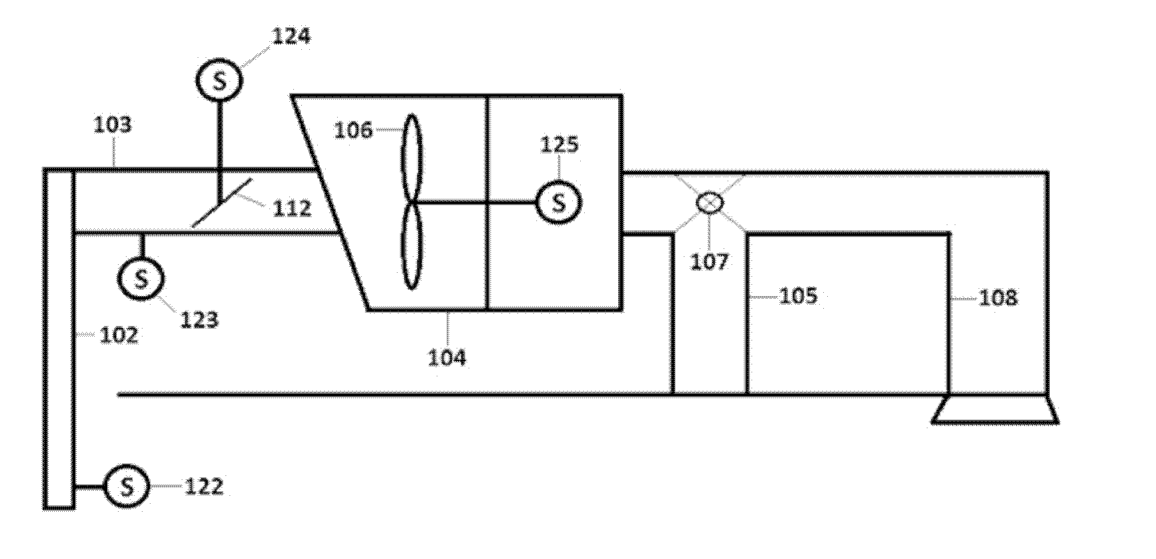
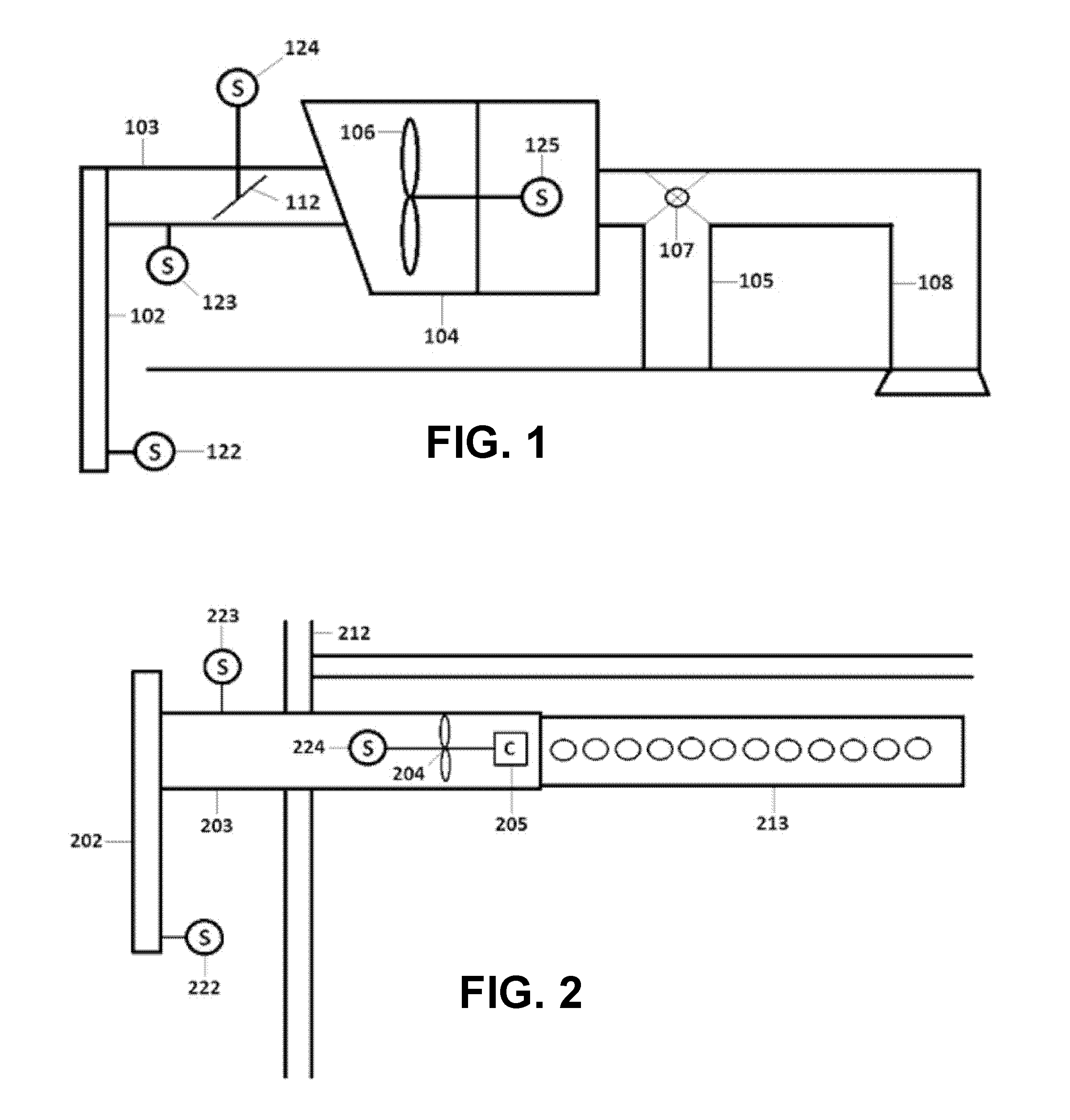
[0017]FIG. 1 is a schematic diagram of a solar hot air system 100 including a thermal collector 102 that allows air to enter the system 100 either at the collector surface via perforations, at the top, side or bottom of the collector cavity via appropriately sized intake vents, or from the interior of the space when recirculation of air through the solar hot air system is used. The thermal collector 102 captures solar energy by heating the air within the collector 102, thereby transferring solar energy to the heated air. The air leaves the thermal collector 102 via a conduit, for example, a duct, grill, or wall penetration 103 connected to the thermal collector 102 and travels to a facility using the heated air, for example, a building. The heated air may enter the building, for example into an existing or fitted air intake system 104. Such an air intake system 104 may already be present or may be added to the building to meet the fresh air demands of the building. As shown in FIG. ...

second embodiment

[0025]FIG. 2 is a schematic diagram of a system 200 according to the present invention. Referring to FIG. 2, the heated air from a solar thermal collector 102 may be directly piped into a building space 212 through a duct 203 and driven by a fan 204 into the space 212 through a distribution duct 213. Such direct piping may displace the need for a fresh air system connected to the space 212 to provide lower temperature fresh air. The controls in FIG. 2 may be connected to temperature monitoring devices and control units that may communicate with existing control technologies of the building to optimize the use of pre-heated air over conditioned air from the heating system of the building.

[0026]In the same or another embodiment, commercially available pre-configured monitoring equipment may be installed to measure the production of the system 200 and usage at the collector 222.

[0027]In the same or another embodiment, one or more sensors may be connected at one or more locations within...


PUM


Abstract

A solar hot air system is provided containing a solar hot air collector and an inlet duct connected to the solar hot air collector and a building fresh air intake. A sensor is connected to the building fresh air intake, configured to measure fan speed and damper position. In addition, a sensor is connected to the inlet duct, configured to measure air volume and temperature. Further, a sensor is connected to the solar hot air collector, configured to measure internal and ambient temperature. A means for calculating a periodic fee to a user based at least in part upon an amount of generated energy is also provided.

Description

CROSS-REFERENCE TO RELATED APPLICATION[0001]This application claims priority to copending U.S. Provisional Application entitled, “SOLAR AIR THERMAL ENERGY SYSTEM AND ENERGY PURCHASE AGREEMENT METHOD,” having Ser. No. 61 / 487,559, filed May 18, 2011, Which is entirely incorporated herein by reference.FIELD OF THE INVENTION[0002]The present invention relates to solar energy and more particularly, is related to providing energy services.BACKGROUND OF THE INVENTION[0003]The price of using fossil fuels and / or electricity to heat buildings has been increasing, is expected to increase and has negative environmental consequences. Many people are looking for alternatives to provide stable and lower costs for heating their facilities.[0004]A building's heating load can be offset using solar heat in passive and active technologies. Passive solar involves design elements allowing solar thermal energy to lower a structure's heat loads. Other technologies, such as geothermal provide additional met...

Claims


Application Information

Patent Timeline
IPC IPC(8): E04D13/18F24J2/04
CPCF24J2/00Y02E10/40Y02B10/20F24S2201/00F24S90/00F24S21/00
Inventor MITCHELL, CLAYTON ROBERTBEHRMANN, MICHAEL JOHNDUNN, MICHAEL ROSCOE
Owner REVOLUTION ENERGY
Why Eureka
Try Eureka