Pulling-wire waterway switching mechanism

a technology of waterway switching and pulling wire, which is applied in mechanical equipment, multiple way valves, transportation and packaging, etc., can solve the problems of inconvenient 360 degree circulation of the driving part directly through pulling wire, and not easy to switch, and achieves convenient switching, simple structure, and convenient to achieve

Inactive Publication Date: 2012-12-20
XIAMEN SOLEX HIGH TECH IND CO LTD +1
View PDF7 Cites 21 Cited by
  • Summary
  • Abstract
  • Description
  • Claims
  • Application Information

AI Technical Summary

Benefits of technology

[0009]A stopping claw, one end is connected to the fixed unit, another end is adaptive to the stopping teeth to prevent the water division body reversing;
[0026]2 The layout is reasonable with simple structure and low space occupation;
[0027]3 The third oblique guiding face is further arranged to ensure completely reset of the reversing of the ratchet shaft, so that the phenomenon that reset cannot fully achieved caused by the non-enough cost of elastic energy can be prevented;

Problems solved by technology

Although one new switching way is disclosed from the technical proposal, the following technical matters are still present: first of all, the layout is complicated; second, to achieve circular switch, the driving part is needed to be rotated 360 degree, but it is inconvenient to achieve the 360 degree circulation of the driving part directly through pulling wire, and it is not easy to switch.

Method used


Image

  • Pulling-wire waterway switching mechanism
  • Pulling-wire waterway switching mechanism
  • Pulling-wire waterway switching mechanism

Examples


Embodiment Construction

[0042]With the following description of the drawings and specific embodiments, the invention shall be further described in details.

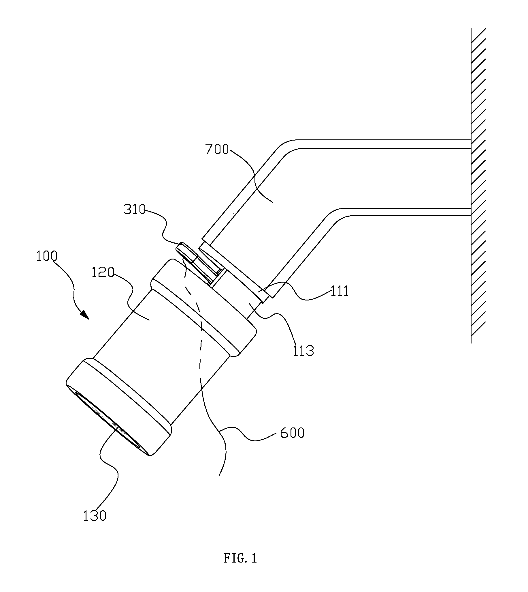
[0043]According to FIG. 1 to FIG. 13, the pulling-wire waterway switching mechanism offered by the preferred embodiment in the present invention is present.

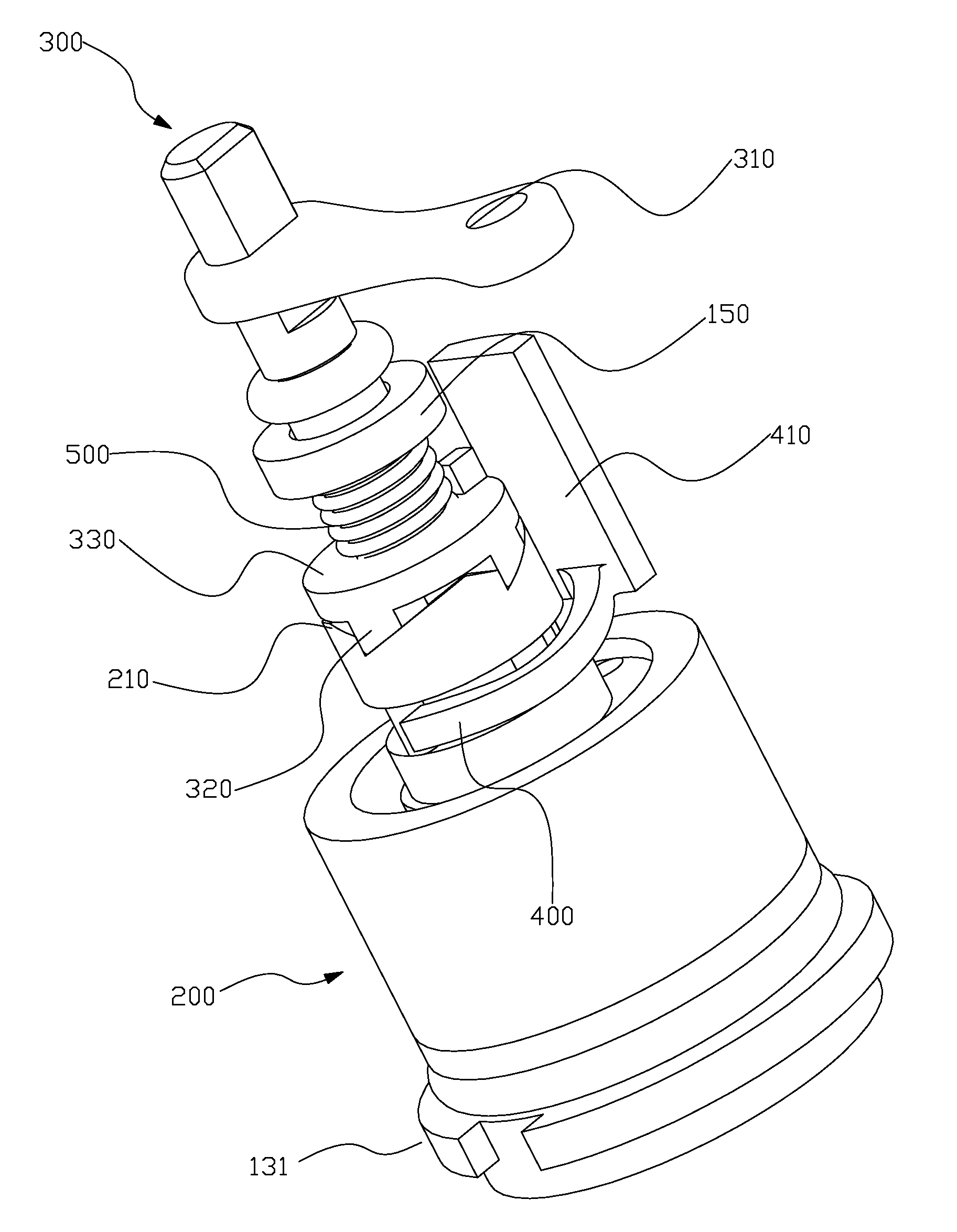
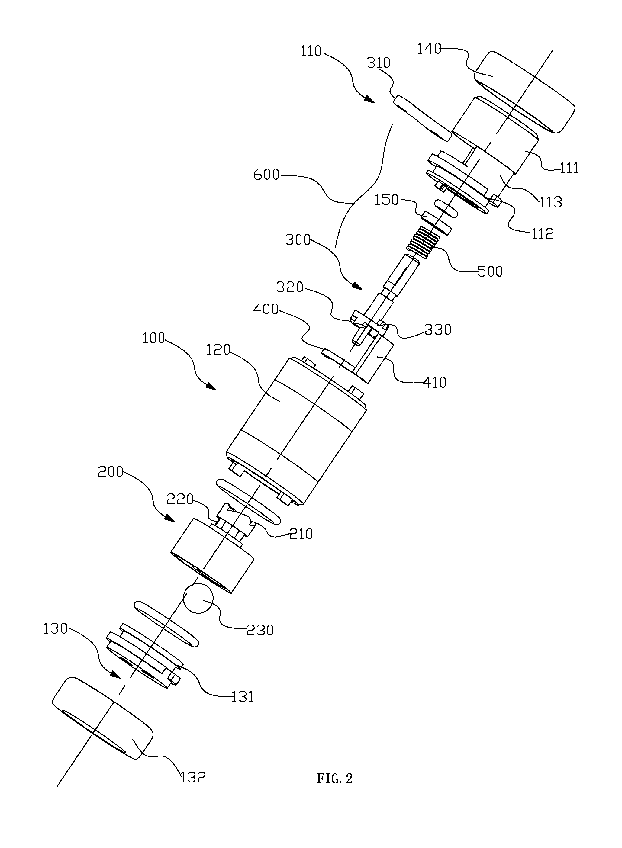
[0044]The pulling-wire waterway switching mechanism comprises a fixed unit 100, a water division body 200, a ratchet shaft 300, a stopping claw 400, a returning body 500 and a pulling-wire 600.

[0045]The fixed unit 100 comprises a connector 110, a main body 120, an outlet terminal 130, a first cover 140 and a check ring 150. The connector 110 is provided with an upper connection seat 111, a lower connection seat 112 and a connecting tube 113, which can be formed in one piece. The upper connection seat 111 is fixed connected to the water resource, such as the American support arm in FIG. 1. The upper end of the connecting tube 113 is fixedly arranged and communicated with the eccentric position of the u...


PUM


Abstract

A pulling-wire waterway switching mechanism has a fixed unit, a water division body, a ratchet shaft, a stopping claw, a returning body and a pulling wire. The water division body can be rotationally arranged in the fixed unit, and can use the rotation between the water division body and the fixed unit to achieve the switch of the outlet functions, a plurality of lower ratchets in anuular array are arranged on the top surface of the water division body, and a plurality of stopping teeth in anuular array are arranged on the outer rotative surface of the water division body. The ratchet shaft provided with a pulling block extending out of the fixed unit and a plurality of upper ratchets in annular array. The pulling block drives the ratchet shaft to rotate forward. The upper ratchets can drive the water division to rotate forward.

Description

FIELD OF THE INVENTION[0001]The present invention relates to a waterway switching mechanism of bathroom equipments, more particularly to a pulling-wire waterway switching mechanism.BACKGROUND OF THE INVENTION[0002]The utility mode <the pulling-wire outlet functions switch shower head> (authorized announcement number CN201143473Y) disclosed by the china patent database on Nov. 5, 2008 mainly comprises the body of the shower head, the outlet panel and the water division system fixed between the body of the shower head and the outlet panel, and also comprises the driving device driving the rotation of the water division system, and a pulling wire is used for pulling the driving part of the driving device to drive the water division system to rotate, more than one through inlet and outlet are simultaneously opened on the corresponding positions of the water division system. The water division system is rotated, so that one inlet of the water division system is communicated with th...

Claims


Application Information

Patent Timeline
Patent Type & Authority Applications(United States)
IPC IPC(8): F16K11/074
CPCE03C1/08E03C1/0408B05B1/18B05B1/1636Y10T137/86863
Inventor ZHOU, HUASONGZHONG, YANHUICHEN, JIANMINCHEN, BIN
Owner XIAMEN SOLEX HIGH TECH IND CO LTD
Why Eureka
Try Eureka