Managing Treatment of Subterranean Zones

a technology for subterranean zones and treatment methods, applied in the direction of fluid removal, borehole/well accessories, insulation, etc., can solve the problems of large energy consumption of steam generated large energy consumption of steam produced for injection into wells, and large cost associated with production of steam

Inactive Publication Date: 2012-12-20
HALLIBURTON ENERGY SERVICES INC
View PDF2 Cites 25 Cited by
  • Summary
  • Abstract
  • Description
  • Claims
  • Application Information

AI Technical Summary

Benefits of technology

[0041]A sixth aspect according to any of the preceding aspects may also include the feature of reducing the virtual heated fluid generation rate based on the determined difference between the feedback and the setpoint being below a threshold value.
[0068]Various embodiments of a control system for managing and / or controlling a system for providing heated fluid to a subterranean zone according to the present disclosure may include one or more of the following features. For example, the control system may more efficiently react to dynamically changing parameters, such as, for example, heated fluid quantity and heated fluid quality. The control systems may also ensure that all or most subsystems of a system for treating a subterranean zone using heated fluid are coordinated. For instance, the control system may ensure coordination between such subsystems (e.g., a compressor subsystem, an air valve subsystem, a fuel valve subsystem) by coupling (i.e., fully or partially) one or more inputs into the control system. Further, the control system may reduce waste heat and lost energy from a system for treating a subterranean zone using heated fluid. As another example, the control system may control one or more components of the subsystems while minimizing energy (e.g., fluid) losses due to, for instance, pressure changes through such components. In addition, the control system may utilize a combination of feedback and feed forward control loops to control one or more subsystems of system for treating a subterranean zone using heated fluid.
[0069]Various embodiments of a control system for managing and / or controlling a system for providing heated fluid to a subterranean zone according to the present disclosure may also include one or more of the following features. The control system may control the components of a system for providing heated fluid to a subterranean zone (e.g., a downhole steam generation system) to account for system inertia. The control system may provide for coupled control of a compressor and valve combination used in a downhole steam operation using a single, nested control loop to more efficiently provide heat fluid to a subterranean zone. The control system may also operate to decouple a desired steam quality parameter from a steam flow rate parameter to control a downhole steam generation system. Further, the control system may also allow for a system for providing heated fluid to a subterranean zone to automatically adjust (e.g., reduce) a virtual heated fluid generation rate to help eliminate and / or balance around system bottlenecks. For example, the control system may provide for substantial synchronization among the subsystems of a downhole steam generation system. As another example, the control system may not be driven by errors in one or more subsystems and / or components of the system for providing heated fluid to a subterranean zone (i.e., a lagging system), but instead may look forward.

Problems solved by technology

Generally, steam generated for injection into a well requires large amounts of energy such as to compress and / or transport air, fuel, and water used to produce the steam.
Much of this energy is largely lost to the environment without being harnessed in any useful way.
Consequently, production of steam has large costs associated with its production.

Method used


Image

  • Managing Treatment of Subterranean Zones
  • Managing Treatment of Subterranean Zones
  • Managing Treatment of Subterranean Zones

Examples


Embodiment Construction

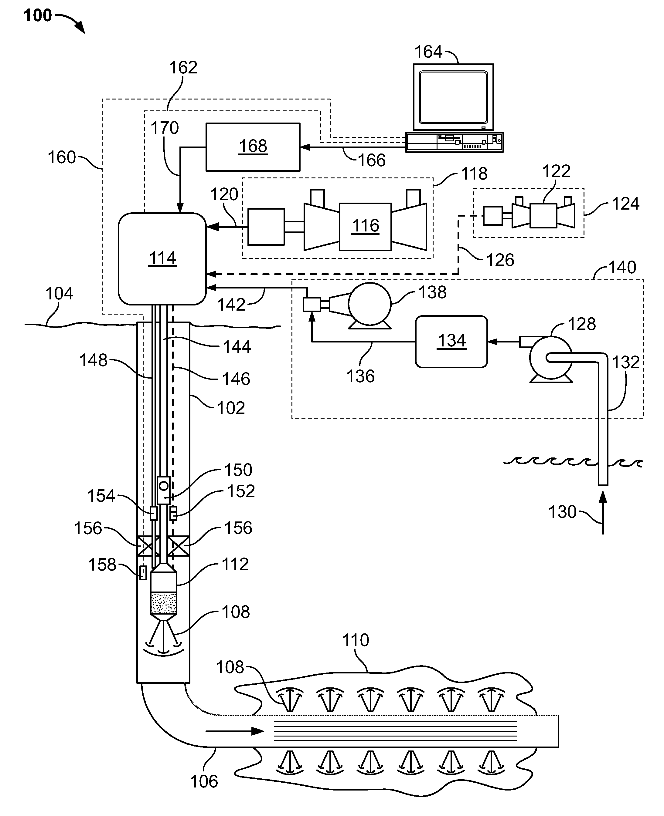
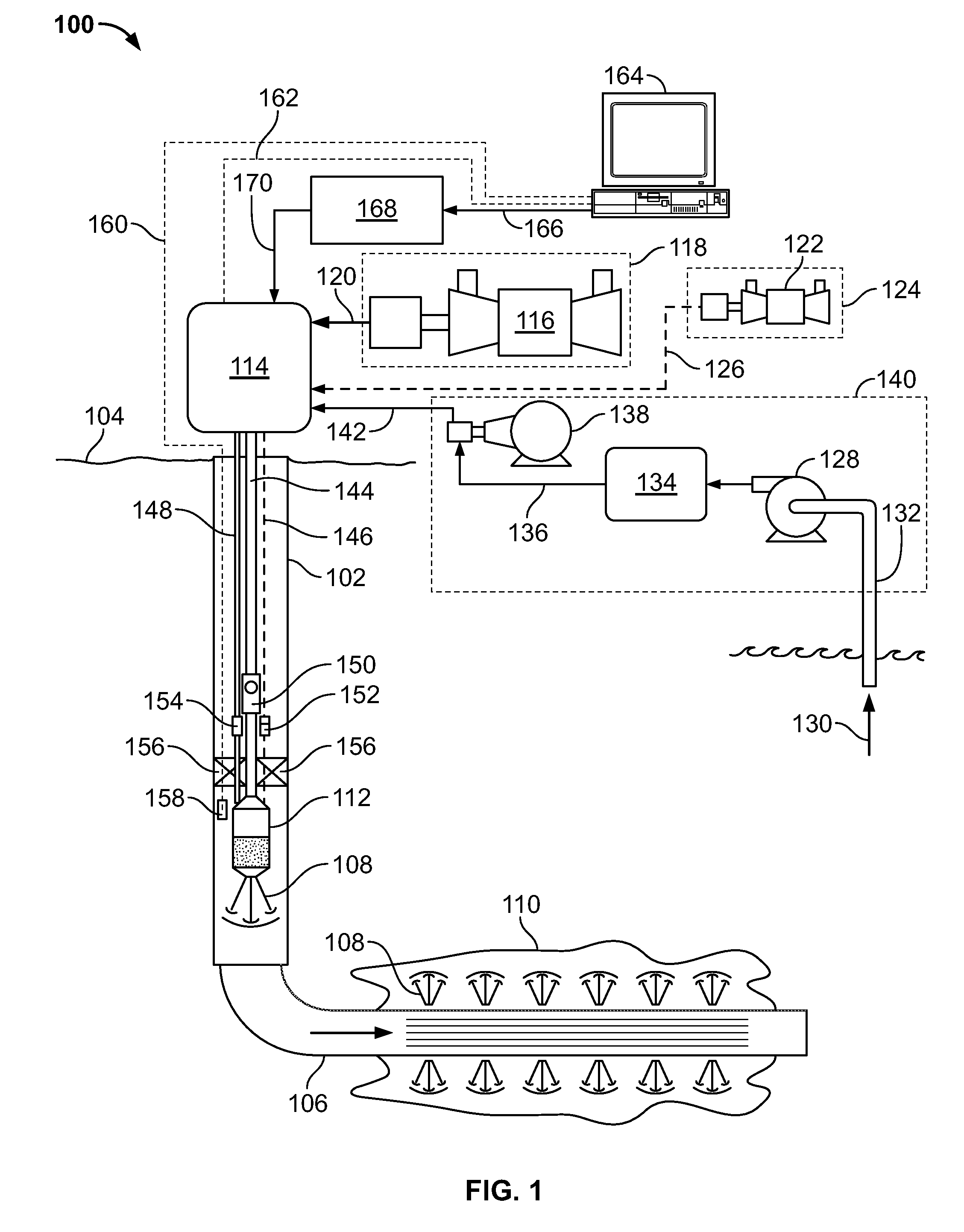
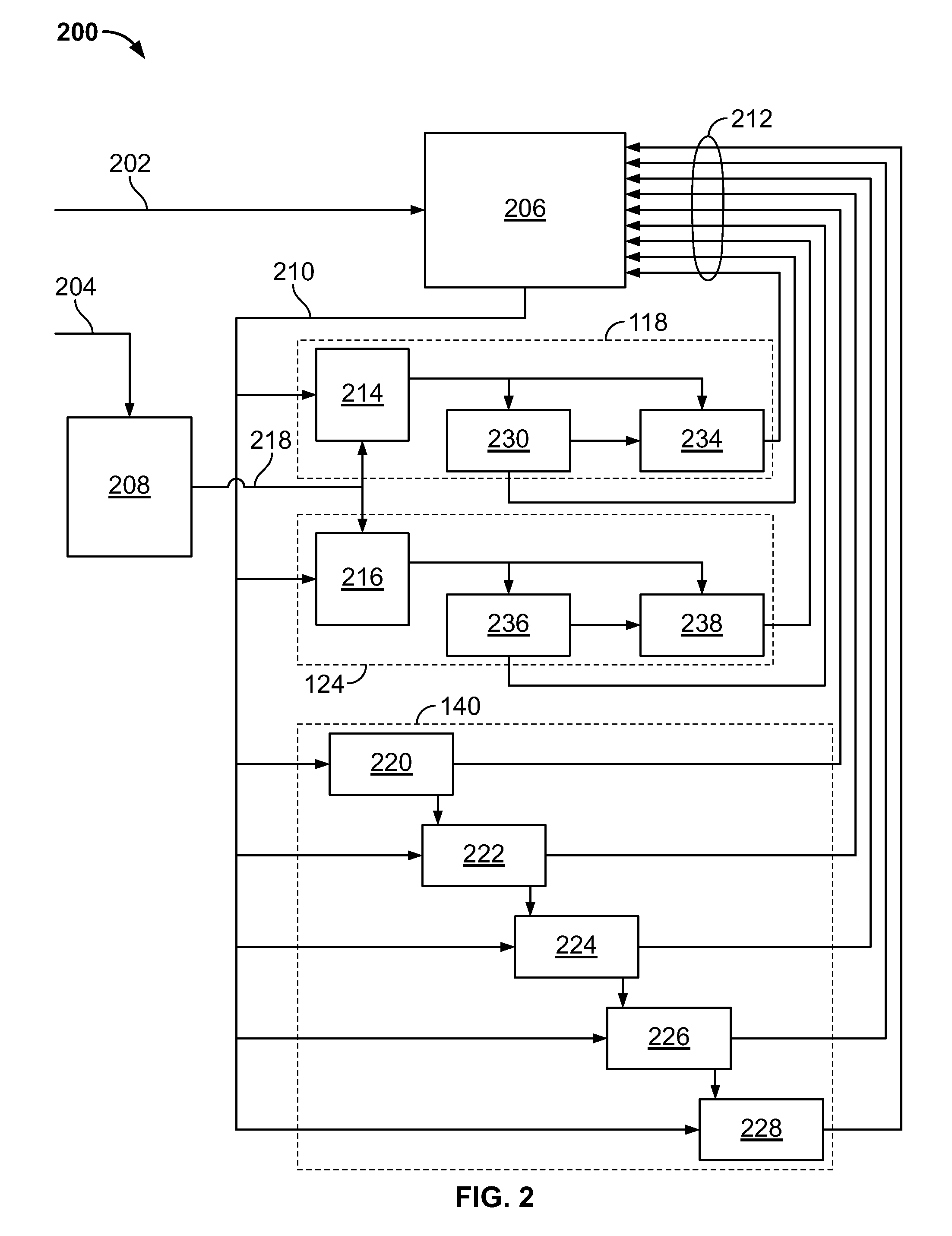
[0009]The present disclosure relates to controlling a system for treating a subterranean zone using heated fluid introduced into the subterranean zone via a well bore. The fluid is heated, in some instances, to form steam. The subterranean zone can include all or a portion of a resource bearing subterranean formation, multiple resource bearing subterranean formations, or all or part of one or more other intervals that it is desired to treat with the heated fluid. The fluid is heated, at least in part, using heat recovered from near-by operation. The heated fluid can be used to reduce the viscosity of resources in the subterranean zone to enhance recovery of those resources. In some embodiments, the system for treating a subterranean zone using heated fluid may be suitable for use in a “huff and puff” process, where heated fluid is injected through the same bore in which resources are recovered. For example, the heated fluid may be injected for a specified period, then resources with...


PUM


Abstract

A downhole heated fluid generation system includes an air subsystem having at least one of an air compressor and an air flow control valve; a fuel subsystem having at least one of a fuel compressor and a fuel flow control valve; a treatment fluid subsystem having a fluid pump; a combustor fluidly coupled to at least one of the air subsystem, the fuel subsystem, or the treatment fluid subsystem, and operable to provide a heated fluid into a wellbore; and a controller operable to receive an input representing a heated fluid parameter; determine a virtual heated fluid generation rate based at least partially on the heated fluid parameter; and control at least one of the air subsystem, the fuel subsystem, or the treatment fluid subsystem by the virtual heated fluid generation rate.

Description

TECHNICAL BACKGROUND[0001]This disclosure relates to managing, directing, and otherwise controlling a treatment of one or more subterranean zones using heated fluid.BACKGROUND[0002]Heated fluid, such as steam, can be injected into a subterranean formation to facilitate production of fluids from the formation. For example, steam may be used to reduce the viscosity of fluid resources in the formation, so that the resources can more freely flow into the well bore and to the surface. Generally, steam generated for injection into a well requires large amounts of energy such as to compress and / or transport air, fuel, and water used to produce the steam. Much of this energy is largely lost to the environment without being harnessed in any useful way. Consequently, production of steam has large costs associated with its production.[0003]Furthermore, a control system for managing, directing, or otherwise controlling a downhole steam generation system often must control a number of components...

Claims


Application Information

Patent Timeline
Patent Type & Authority Applications(United States)
IPC IPC(8): E21B36/00
CPCE21B43/24
Inventor DYKSTRA, JASON D.FRIPP, MICHAEL LINLEY
Owner HALLIBURTON ENERGY SERVICES INC
Why Eureka
Try Eureka