High efficiency buck-boost power converter
a high-efficiency, buck-boost technology, applied in the direction of power conversion systems, dc-dc conversion, instruments, etc., can solve the problems of significant switching loss and significant ripple in the output voltage vout, and achieve the effect of reducing switching loss and conduction loss, extending the switching period of switches, and reducing switching loss
- Summary
- Abstract
- Description
- Claims
- Application Information
AI Technical Summary
Benefits of technology
Problems solved by technology
Method used
Image
Examples
first embodiment
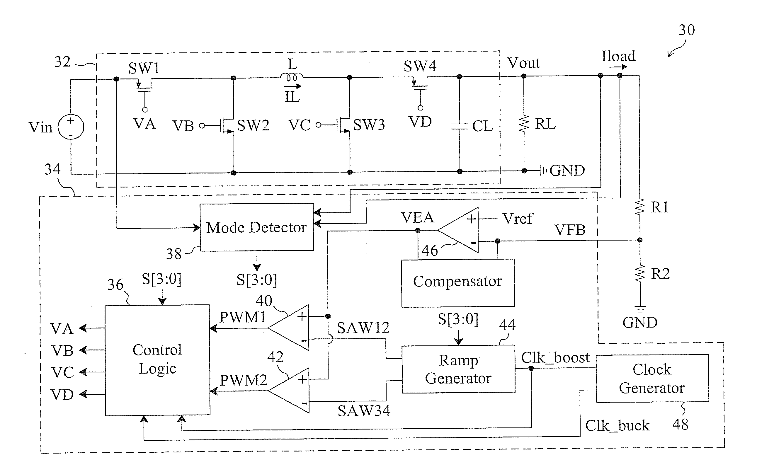
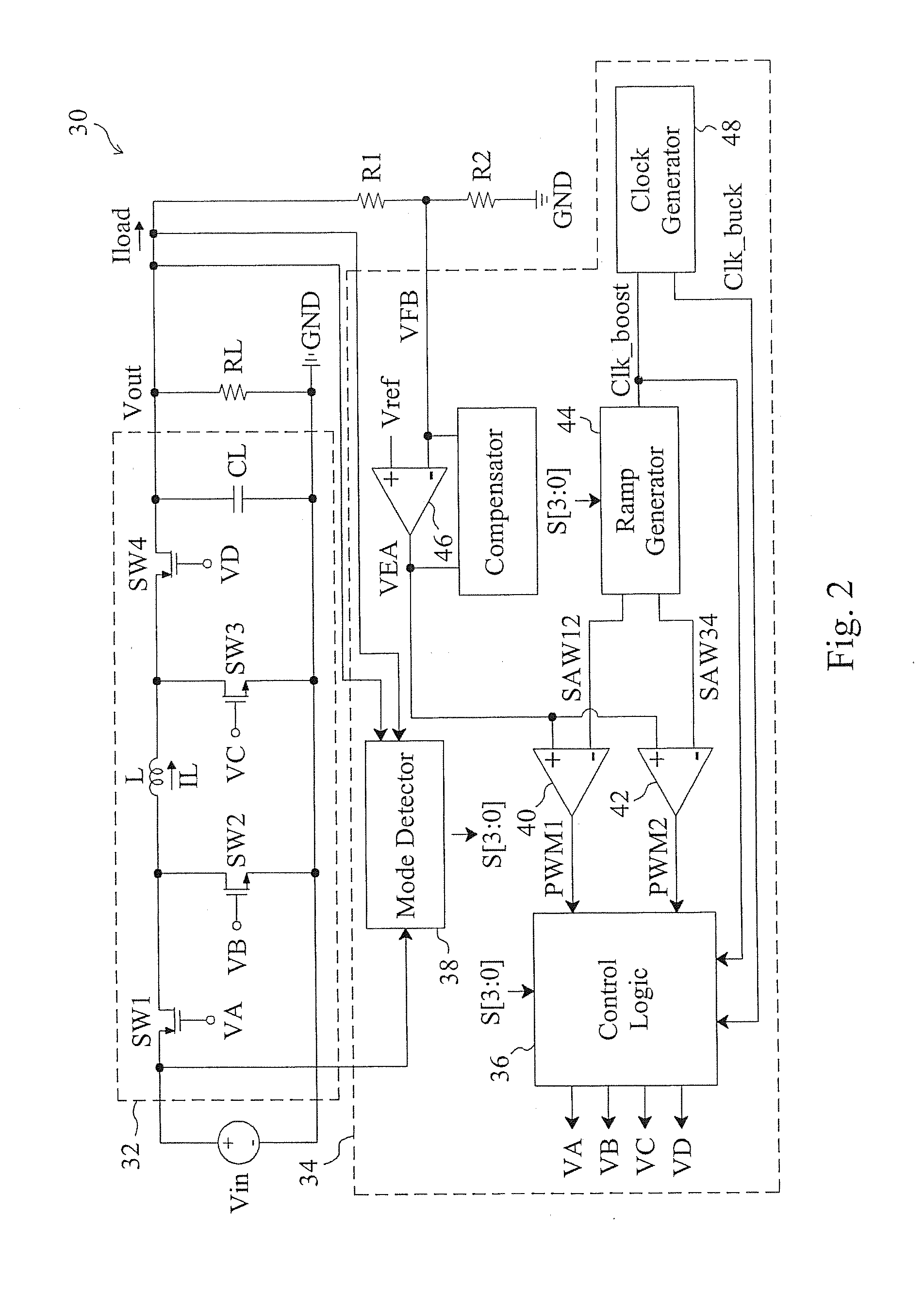
[0027]A first embodiment according to the present invention is shown in FIG. 2, in which a buck-boost power converter 30 includes a control circuit 34 to provide control signals VA, VB, VC and VD to drive a power stage 32, so as to convert an input voltage Vin into an output voltage Vout that is divided by voltage divider resistors R1 and R2 to generate a feedback signal VFB for the control circuit 34. In the power stage 32, a switch SW1 is coupled between the power input terminal Vin and an inductor L, switches SW2 and SW3 are coupled between two terminals of the inductor L and a ground terminal GND respectively, and a switch SW4 is coupled between the inductor L and the power output terminal Vout. The duty of the entire system is not only related to the input voltage Vin and the output voltage Vout, but also affected by a load current Iload. Therefore, according to the present invention, the load current Iload is also taken into account when determining the time points at which th...
second embodiment
[0039]By replacing the switch SW4 in the buck-boost power converter 30 of FIG. 2 with a diode D1, a second embodiment according to the present invention is provided as shown in FIG. 13. The control and operation of this buck-boost power converter 130 is similar to that of the buck-boost power converter 30 of FIG. 2. When the buck-boost power converter 130 operates in the buck-boost modes, the switches SW1-SW3 are switched in the sequence that (1) the switch SW2 is turned on and the switches SW1, SW3 are turned off, (2) the switch SW1 is turned on and the switches SW2, SW3 are turned off, and (3) the switches SW1, SW3 are turned on, and the switch SW2 is turned off. These steps 1-3 are repeated in the same sequence. When the voltage ratio between the two terminals of the inductor L, determined by the input voltage Vin, the output voltage Vout, and the load current Iload, is greater than a first threshold value but smaller than one, the switch SW3 has a fixed duty. When the voltage ra...
third embodiment
[0040]By replacing the switch SW2 in the buck-boost power converter 30 of FIG. 2 with a diode D2, a third embodiment according to the present invention is provided as shown in FIG. 14. The control and operation of this buck-boost power converter 140 is similar to that of the buck-boost power converter 30 of FIG. 2. When the power converter 140 operates in the buck-boost modes, the switches SW1, SW3, SW4 are switched in the sequence that (1) the switch SW4 is turned on and the switches SW1, SW3 are turned off, (2) the switches SW1, SW4 are turned on and the switch SW3 is turned off, and (3) the switches SW1 and SW3 are turned on and the switch SW4 is turned off. These steps 1-3 are repeated in the same sequence. When the voltage ratio between the two terminals of the inductor L, determined by the input voltage Vin, the output voltage Vout, and the load current Iload, is greater than a first threshold value but smaller than one, each of the switches SW3 and SW4 has a fixed duty. When ...
PUM
 Abstract
Description
Claims
Application Information
 - R&D
- Intellectual Property
- Life Sciences
- Materials
- Tech Scout
- Unparalleled Data Quality
- Higher Quality Content
- 60% Fewer Hallucinations
Browse by: Latest US Patents, China's latest patents, Technical Efficacy Thesaurus, Application Domain, Technology Topic, Popular Technical Reports.
© 2025 PatSnap. All rights reserved.Legal|Privacy policy|Modern Slavery Act Transparency Statement|Sitemap|About US| Contact US: help@patsnap.com


