Antenna with adjustable beam characteristics

a beam characteristic and adjustable technology, applied in the direction of antennas, differentially interacting antenna combinations, antenna details, etc., can solve the problem of relative complexity of mechanical designs, and achieve the effect of simple design and flexible design

Active Publication Date: 2012-12-20
TELEFON AB LM ERICSSON (PUBL)
View PDF17 Cites 64 Cited by
  • Summary
  • Abstract
  • Description
  • Claims
  • Application Information

AI Technical Summary

Benefits of technology

[0008]An object with the present invention is to provide an antenna with adjustable beam characteristics that is more flexible and have a simpler design compared to prior art solutions.

Problems solved by technology

Current implementations of these features are based on mechanically rotating or moving parts of the antenna which results in relatively complicated mechanically designs.

Method used


Image

  • Antenna with adjustable beam characteristics
  • Antenna with adjustable beam characteristics
  • Antenna with adjustable beam characteristics

Examples


example 1

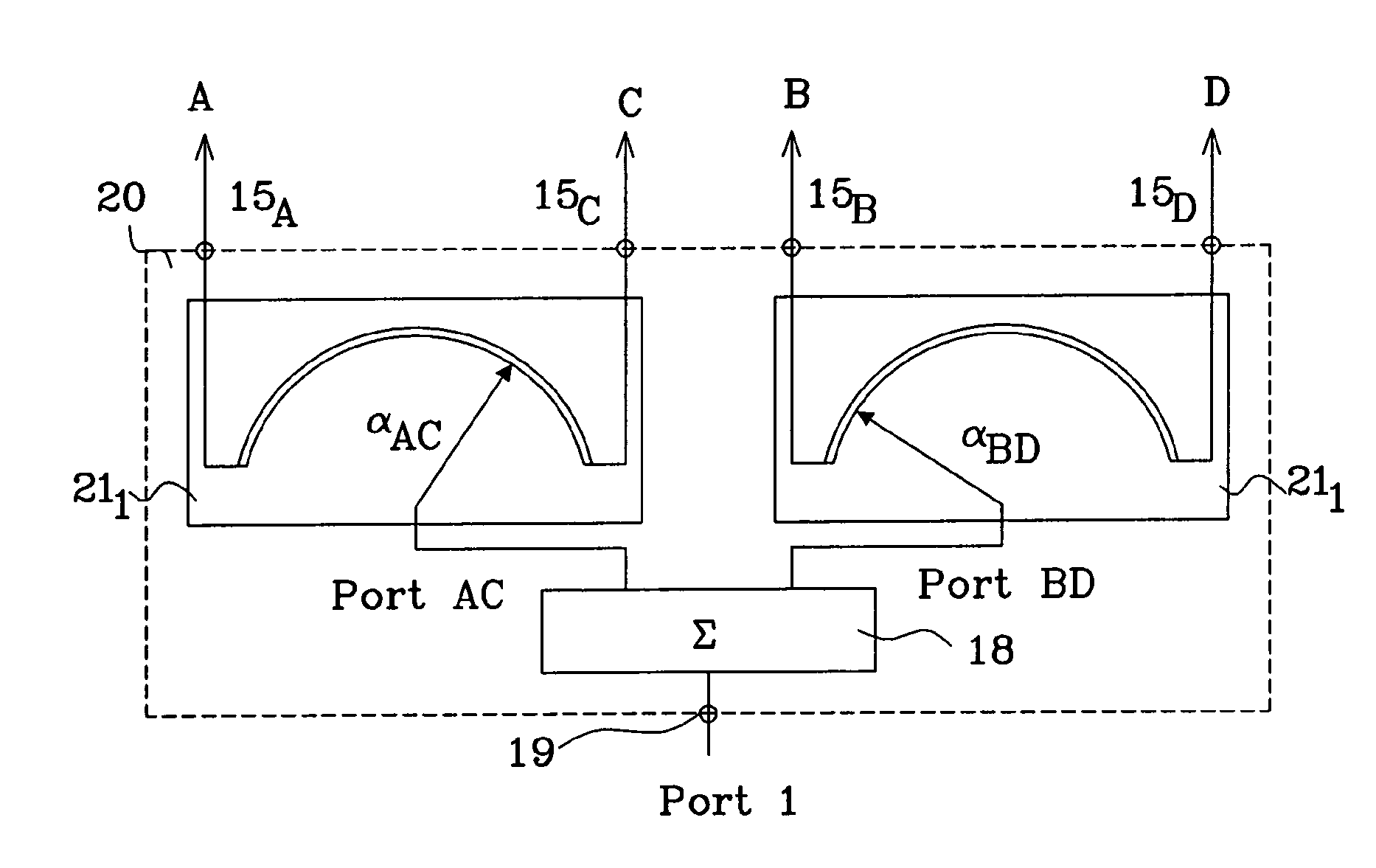
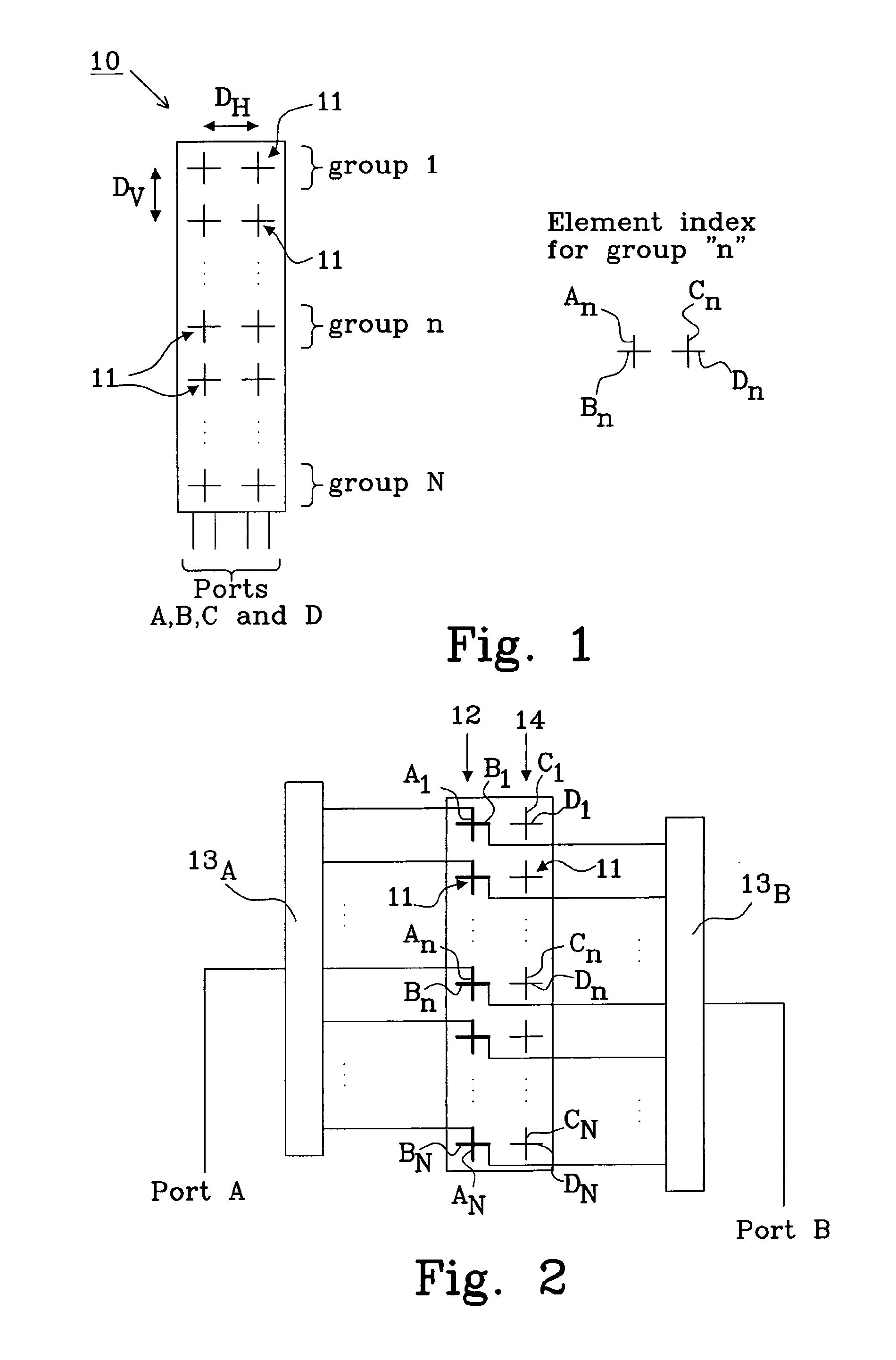
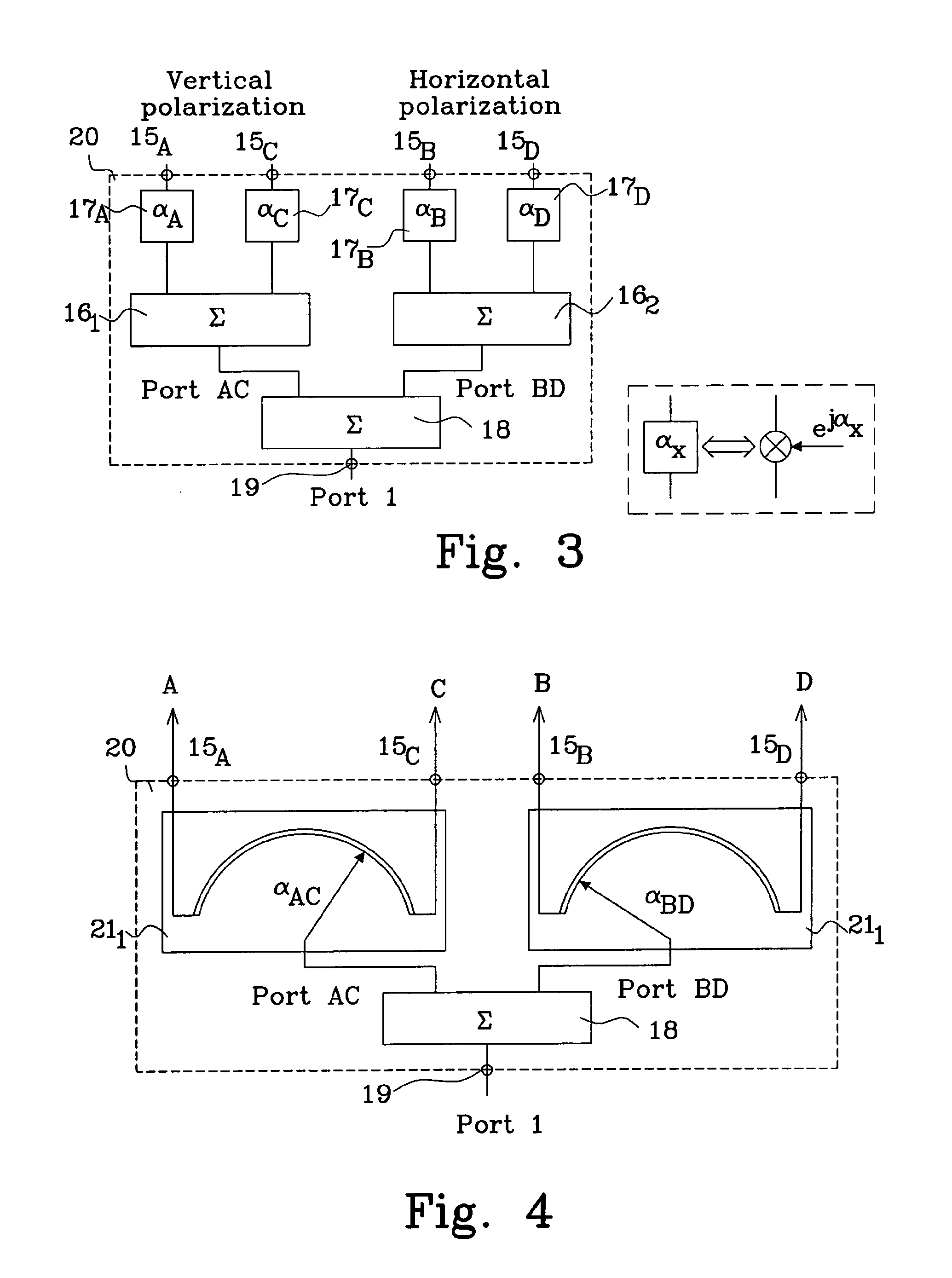
[0059]As an example, a first single beam antenna as described in connection with FIGS. 1-4, is simulated in which the number of array elements in each column is 12 (i.e. N=12) and the column separation DH between array elements, and thus the distance between first and second phase centres arranged in different columns, is selected to be half a wavelength (DH=0.5λ), and assuming a radiating element pattern with a half power beam width of 90°.

[0060]FIG. 5 shows predicted azimuth beam patterns for the first single beam antenna and the variable phases:

αAC=−αBD=α

for different angles α expressed in terms of the spatial beam pointing angle φ(α). Curve (0;0) denotes φ(αAC)=φ(αBD)=0, curve (17;−17) denotes φ(αAC)=−φ(αBD)=17, curve (23;−23) denotes φ(αAC)=−φ(αBD)=23, curve (27;−27) denotes φ(αAC)=−φ(αBD)=27, and curve (30;−30) denotes φ(αAC)=−φ(αBD)=30. For the azimuth beam patterns the half power beam width is 50, 56, 65, 77 and 90 degrees, respectively.

[0061]FIG. 6 shows the corresponding e...

example 2

[0064]As a further example, a second single beam antenna as described in connection with FIGS. 1-4, in which the number of array elements in each column is 12 (i.e. N=12) and the column separation DH between array elements, and thus the distance between first and second phase centres arranged in different columns, is selected to be seven tenths of a wavelength (DH=0.7λ), and assuming a radiating element pattern with a half power beam width of 65°.

[0065]FIG. 9 shows predicted azimuth beam patterns for the second single beam antenna and the variable phases:

αAC=−αBD=α

for different angles α expressed in terms of the spatial beam pointing angle φ(α). Curve (0;0) denotes φ(αAC)=φ(αBD)=0, curve (13;−13) denotes φ(αAC)=−φ(αBD)=13, curve (19;−19) denotes φ(αAC)=−φ(αBD)=19, curve (22;−22) denotes φ(αAC)=−φ(αBD)=22, and curve (23;−23) denotes φ(αAC)=−φ(αBD)=23. For the azimuth beam patterns the half power band width is 35, 41, 55, 71, and 83 degrees, respectively.

[0066]FIG. 10 shows predicted ...

example 3

[0074]As an example, a first dual beam antenna as described in connection with FIGS. 11-13, in which the number of array elements in each column is 12 (i.e. M=6) and the column separation DH between array elements, and thus the distance between first and second phase centres arranged in different columns, is selected to be half of a wavelength (DH=0.5λ), and assuming a radiating element pattern with a half power beam width of 90°.

[0075]FIG. 14 shows predicted azimuth beam patterns for the first dual beam antenna and variable phases:

αA−αG=αF−αD=αB−αH=αE−αC=α

for different angles α expressed in terms of the spatial beam pointing angle φ(α). Curve 1 (0;0) and curve 2 (0;0), which denotes φ=0 for each antenna port, overlap and similarly curve 1 (17;−17) and curve 2 (−17;17), curve 1 (23,−23) and curve 2 (−23;23), curve 1 (27;−27) and curve 2 (−27;27), and curve 1 (30;−30) and curve 2 (−30;30) are pair-wise identical, i.e., the radiation patterns associated with antenna ports 1 and 2 over...


PUM


Abstract

The present invention relates to an antenna comprising multiple array elements with a first and second feeding point, each associated with orthogonal polarizations, each array element has a first and second phase centre each associated with the orthogonal polarizations, the first and second phase centres of said array elements are arranged in at least two columns, and one antenna port connected to the first and second feeding points of at least two array elements with first phase centre and second phase centre arranged in the at least two columns via a respective feeding network. The feeding network comprises a beam forming network having a primary connection, connected to the antenna port, and at least four secondary connections. The beam forming network divides power between the first feeding point and the second feeding point and controls phase shift differences between the respective feeding points with phase centre arranged in different columns.

Description

TECHNICAL FIELD[0001]The present invention relates to an antenna with adjustable beam characteristics, such as beam width and beam pointing. The invention also relates to a communication device and communication system provided with such an antenna.BACKGROUND[0002]Almost all base station antennas used for mobile communication up till now have, by design, more or less fixed characteristics. One exception is electrical beam tilt which is a frequently used feature. In addition some products exist for which beam width and / or direction can be changed.[0003]Deploying antennas where characteristics (parameters) can be changed, or adjusted, after deployment is of interest since they make it possible to:[0004]Tune the network by changing parameters on a long term basis[0005]Tune the network on a short term basis, for example to handle variations in traffic load over twenty-four hours.[0006]Thus, there is a need to be able to adjust beam width and to adjust beam pointing direction to achieve ...

Claims


Application Information

Patent Timeline
Patent Type & Authority Applications(United States)
IPC IPC(8): H01Q21/24
CPCH01Q1/246H01Q21/26H01Q3/26H01Q3/267H01Q25/001H01Q21/29H01Q3/34H01Q3/40
Inventor JOHANSSON, STEFANJOHANSSON, MARTINPETERSSON, SVEN OSCAR
Owner TELEFON AB LM ERICSSON (PUBL)
Why Eureka
Try Eureka