Light assembly

a technology of light assembly and assembly plate, which is applied in the direction of fixed installation, lighting and heating apparatus, lighting support devices, etc., can solve the problems of low luminous efficiency of halogen lamps, inability to meet the requirements of energy saving, and high cost of halogen lamps, so as to prevent wire corrosion, facilitate the assembly process, and prevent the effect of corrosion

Inactive Publication Date: 2012-12-20
KUAN CHUAN CHING
View PDF1 Cites 4 Cited by
  • Summary
  • Abstract
  • Description
  • Claims
  • Application Information

AI Technical Summary

Benefits of technology

[0014]The light assembly of the present invention has the following advantages: the components of the light assembly are individually installed and made by different material in view of heat dissipation characteristics thereof; the substrate board with a recessed shape can avoid the light from scattering; the elastic steel ring is used to secure the substrate board so that the substrate board will not become loose by impact or shaking; the assembling process is easy and the color of the substrate board can be easily changed or replaced according to ...

Problems solved by technology

The halogen lamp is often used in the conventional light assemblies, and however, the halogen lamp has the following disadvantages:(1) The halogen lamp has low luminous efficiency, which cost a lot of energy, and this point of view, the halogen lamps do not meet the requirements of energy saving.(2) The ray of the halogen lamp can concentrate into a single hot spot, which may cause the poison gas to be discharged from the decoration materials (such as wood, and plastics) and the sticky substance therein, and some materials even can be burned at high temperature.
Furthermore, the heat produced from the halogen lamp in a room can cause the air conditioner to run longer than necessary.(3) The halogen lamp has a thi...

Method used


Image

  • Light assembly
  • Light assembly
  • Light assembly

Examples


Embodiment Construction

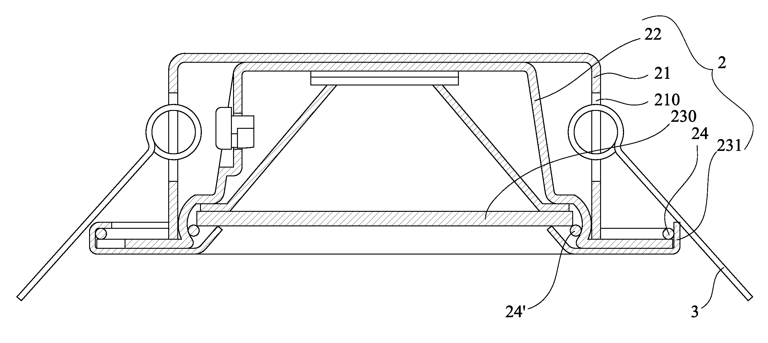
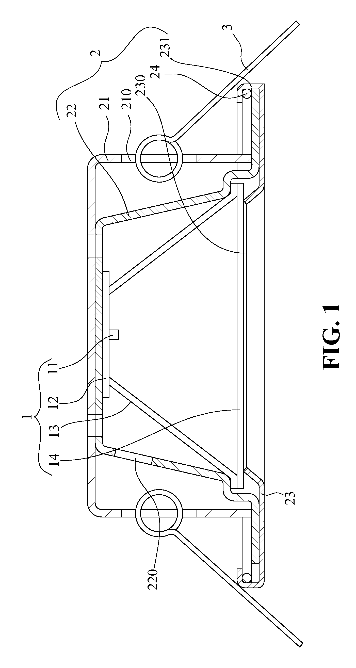
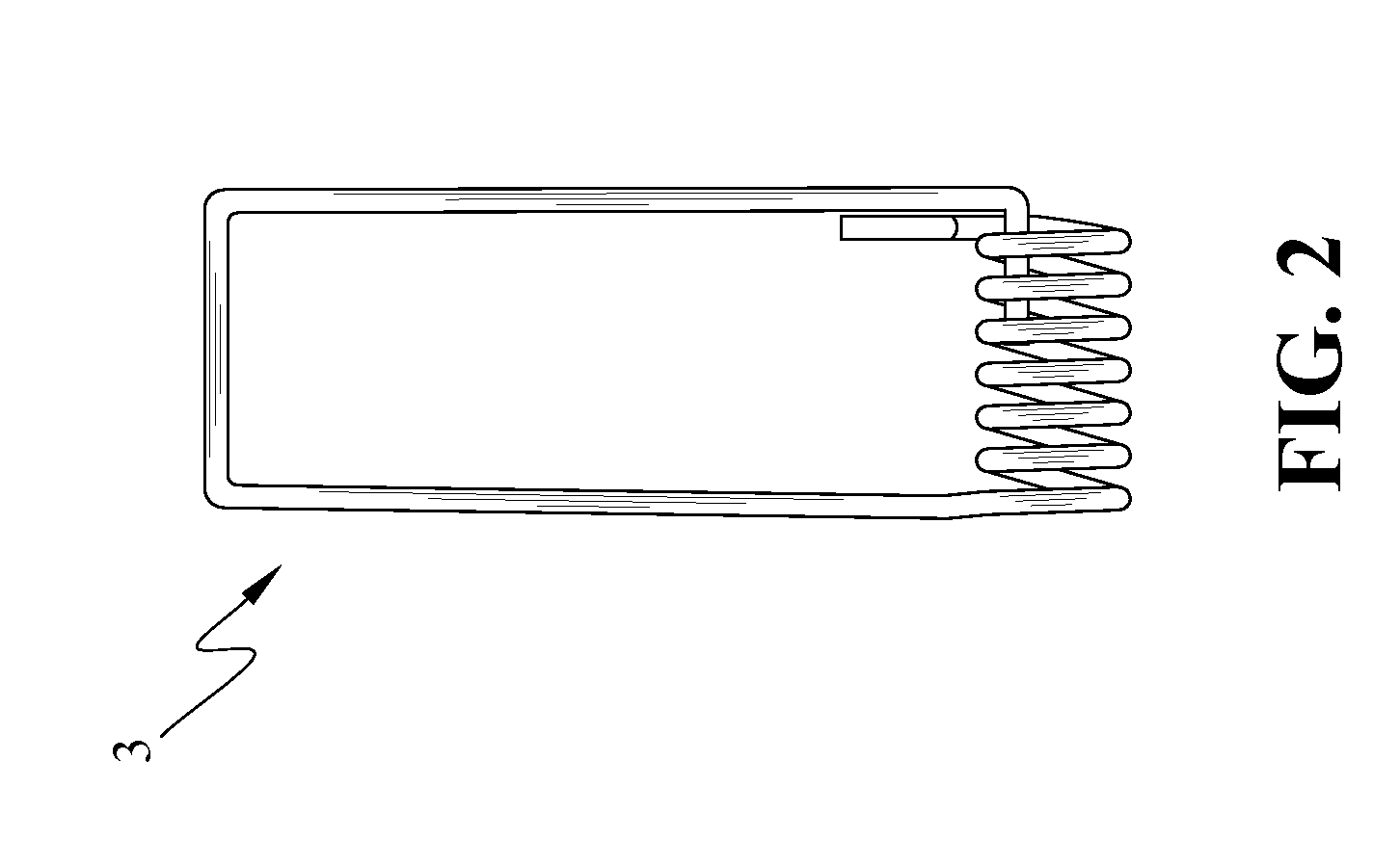
[0023]Referring to FIG. 1, the light assembly of the present invention comprises a fixing unit 2 which is received in an inset hole in the wall (not shown), and the fixing unit 2 has a frame 21 (as shown in FIG. 4) and a plurality of torsion springs 3 (as shown in FIG. 2) are connected to the side of the frame 21. A first end of each torsion spring 3 is provided in an opening 210 in the side of the frame 21, and a second end of each torsion spring 3 is fastened to a fastener (not shown) in the inset hole in the wall. A lamp cover 22 (as shown in FIG. 6) is disposed in the frame 21 and has at least one wire hole 220 to allow the wires to pass through it. The substrate board 23 with a recessed shape is disposed at the opening of the frame 12 (as shown in FIG. 5) and has an opening 230 formed therein, and the external peripheral of the substrate board 23 has a hook flange 231. An elastic steel ring 24 (as shown in FIG. 3) is tightly fastened to the hook flange 231 of the substrate boar...


PUM


Abstract

A light assembly includes a fixing unit and a lighting unit located within a lamp cover. The fixing unit includes a substrate board with a recessed shape, and an elastic steel ring is engaged with the hook flange of the substrate board in order to increase the tightness between the substrate board and the lamp cover so as to prevent water vapor and salt mist from entering into the light assembly, and thereby the corrosion of light source and circuit can be avoided. The light emitting diode is used as a light source instead of the conventional halogen lamp.

Description

BACKGROUND OF THE INVENTION[0001]1. Field of the Invention[0002]The present invention relates generally to a light assembly, and in particular to a light assembly which can avoid water vapor and salt mist from entering therein.[0003]2. The Prior Arts[0004]The halogen lamp is often used in the conventional light assemblies, and however, the halogen lamp has the following disadvantages:[0005](1) The halogen lamp has low luminous efficiency, which cost a lot of energy, and this point of view, the halogen lamps do not meet the requirements of energy saving.[0006](2) The ray of the halogen lamp can concentrate into a single hot spot, which may cause the poison gas to be discharged from the decoration materials (such as wood, and plastics) and the sticky substance therein, and some materials even can be burned at high temperature. Furthermore, the heat produced from the halogen lamp in a room can cause the air conditioner to run longer than necessary.[0007](3) The halogen lamp has a thick...

Claims


Application Information

Patent Timeline
IPC IPC(8): F21V19/02
CPCF21V31/00F21S8/02F21V21/04F21Y2115/10
Inventor KUAN, CHUAN-CHING
Owner KUAN CHUAN CHING
Why Eureka
Try Eureka