
Method and apparatus for channel measurement

Active Publication Date: 2012-12-20
HUAWEI TECH CO LTD
View PDF4 Cites 26 Cited by
  • Summary
  • Abstract
  • Description
  • Claims
  • Application Information

AI Technical Summary

Benefits of technology

[0007]To improve effectiveness and accuracy of channel measurement and feedback, embodiments of the present invention provide a method and an apparatus for channel measurement. The technical solutions are as follows:
[0034]The technical solutions provided in the embodiments of the present invention produce the following beneficial effect: The base station determines the size of the measured bandwidth of the terminal and the location of the measured bandwidth in the system bandwidth, and the size of the measured sub-band and / or the quantity or sizes of measured sub-band sets, and notifies the information to the terminal; according to the information, the terminal performs measurement, thereby preventing invalid feedback and improving effectiveness and accuracy of channel measurement and feedback.

Problems solved by technology

Therefore, accuracy of the measurement result directly affects system performance.
Therefore, the measurement of the channel state within the entire system bandwidth is not accurate.
This results in invalid feedback and wastes the uplink signaling resources.
In this case, the interference produced at the 5 M+3 M−7 M bandwidth affects the accuracy of the channel measurement.
This results in invalid feedback and wastes the uplink signaling resources.
In conclusion, in the prior art, the system bandwidth is taken as the measurement object, which may cause inaccuracy of the measurement and invalid feedback in some scenarios, for example, low load and CA.

Method used


Image

  • Method and apparatus for channel measurement
  • Method and apparatus for channel measurement
  • Method and apparatus for channel measurement

Examples


embodiment 1

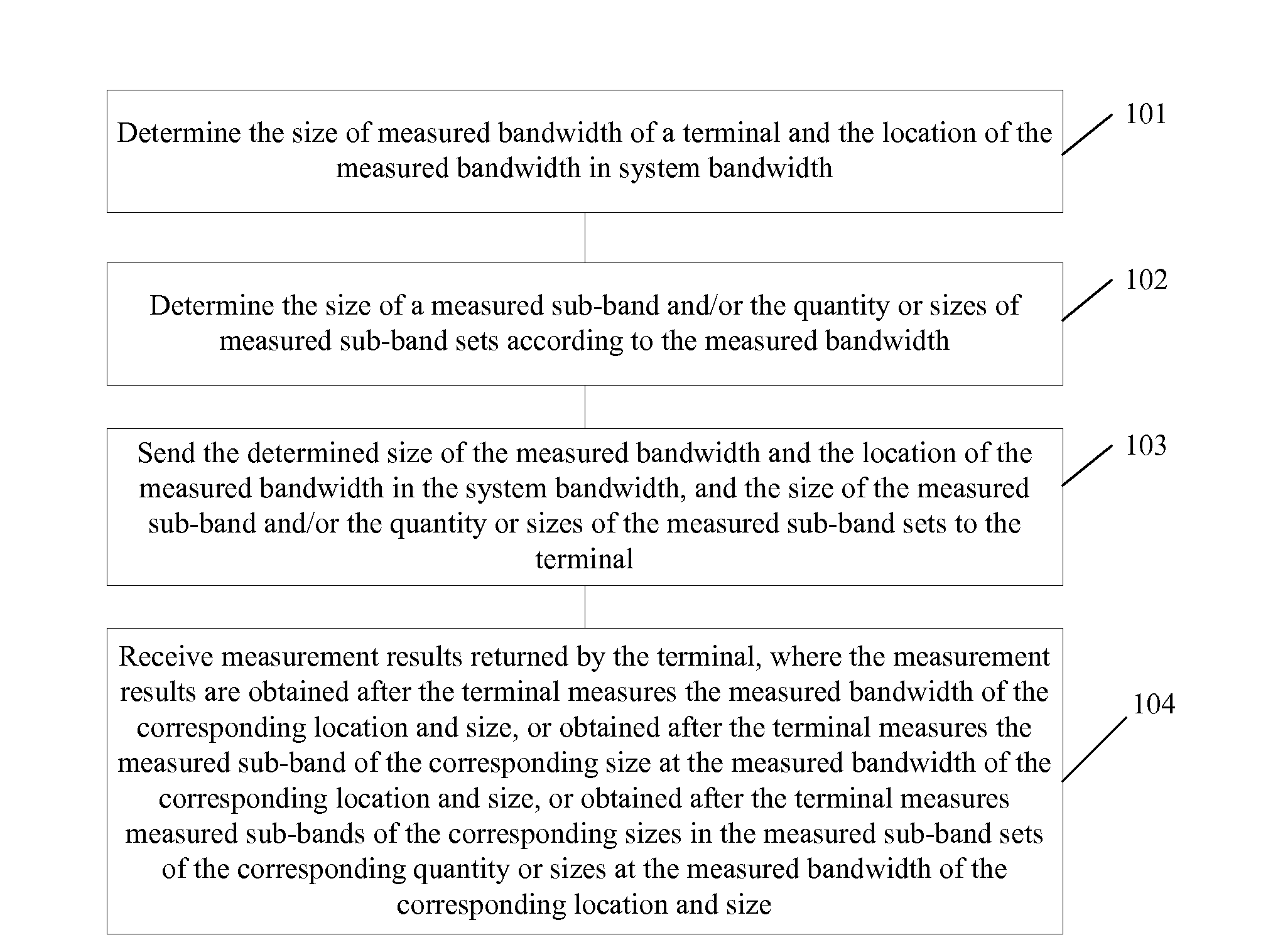
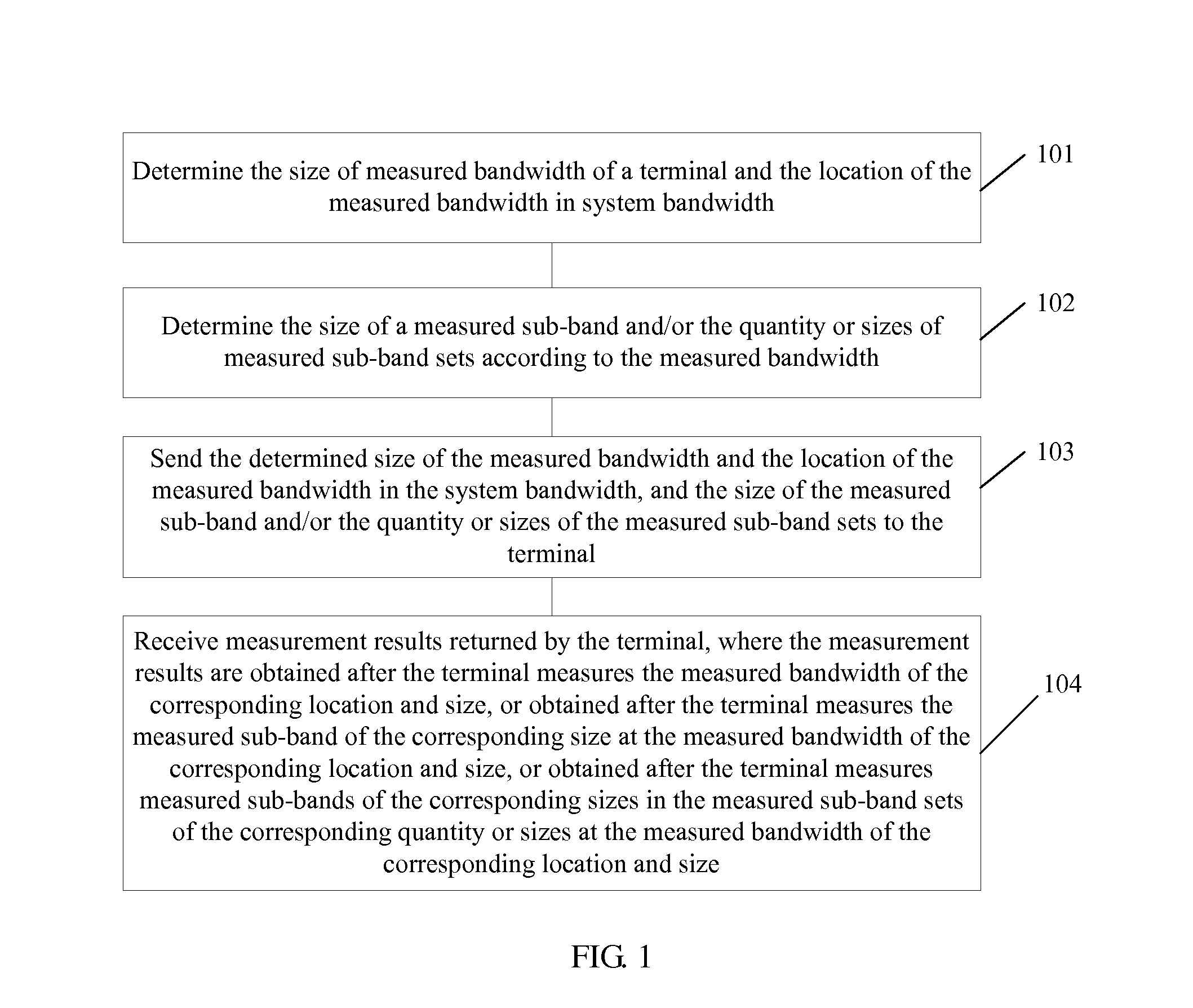
[0043]Referring to FIG. 1, this embodiment provides a method for channel measurement, including the following steps:

[0044]101. Determine the size of measured bandwidth of a terminal and the location of the measured bandwidth in system bandwidth.

[0045]The system bandwidth refers to the length of the frequency supported and sent in a broadcast message by a wireless communication system. For example, the maximum system bandwidth in an LTE system is 20 M, or the system bandwidth in another length.

[0046]The measured bandwidth refers to a part of frequency resources determined by a base station in the system bandwidth and a terminal is allowed to perform channel measurement and feedback by using only these frequency resources. The measured bandwidth may be a section of continuous frequency resources at the system bandwidth, or may be composed of multiple distributed sections of continuous frequency resources. In addition, the measured bandwidth may be cell-specific. Terminals in different...

embodiment 2

[0058]Referring to FIG. 3, this embodiment provides a method for channel measurement, including the following steps:

[0059]301. A base station determines the size of measured bandwidth of a terminal and the location of the measured bandwidth in system bandwidth.

[0060]The definitions of the system bandwidth, measured bandwidth, sub-band can refer to steps 101 and 102, which are not detailed herein.

[0061]Through this step, the terminal can perform channel measurement within the range of the measured bandwidth, so as to improve accuracy and effectiveness of measurement results, and save uplink signaling resources.

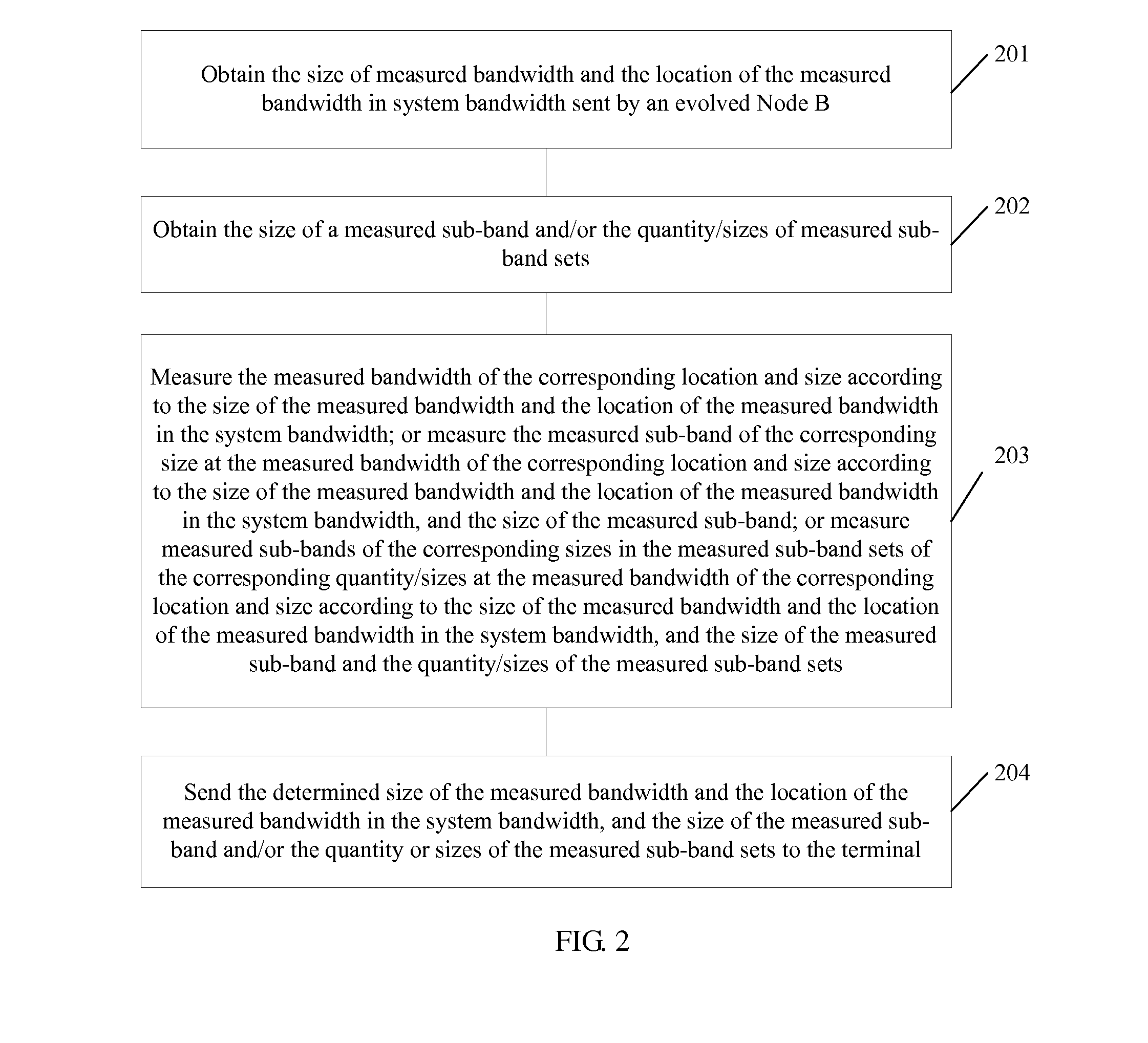
[0062]302. The base station determines the size of a measured sub-band and / or the quantity / sizes of measured sub-band sets according to the measured bandwidth.

[0063]When the size of the measured sub-band is determined according to the measured bandwidth, the size of the measured sub-band determined according to the measured bandwidth is generally smaller than the size that is d...

embodiment 4

[0103]Referring to FIG. 4, this embodiment provides an apparatus for channel measurement, including:

[0104]a bandwidth information determining module 401, configured to determine the size of measured bandwidth of a terminal and the location of the measured bandwidth in system bandwidth;

[0105]a sub-band information determining module 402, configured to determine the size of a measured sub-band and / or the quantity / sizes of measured sub-band sets according to the measured bandwidth determined by the bandwidth information determining module 401;

[0106]a sending module 403, configured to send the size of the measured bandwidth and the location of the measured bandwidth in the system bandwidth that are determined by the bandwidth information determining module 401, and the size of the measured sub-band and / or the quantity / sizes of measured sub-band sets that are determined by the sub-band information determining module 402 to the terminal; and

[0107]a receiving module 404, configured to rece...


PUM


Abstract

The present invention discloses a method for channel measurement which includes: determining the size of measured bandwidth of a terminal and the location of the measured bandwidth in system bandwidth; determining the size of a measured sub-band and / or the quantity or sizes of measured sub-band sets according to the measured bandwidth; sending the determined size of the measured bandwidth and the location of the measured bandwidth in the system bandwidth, and the size of the measured sub-band and / or the quantity or sizes of the measured sub-band sets to the terminal; receiving measurement results returned by the terminal With the method provided in the present invention, invalid feedback is prevented and effectiveness and accuracy of channel measurement and feedback are improved.

Description

CROSS-REFERENCE TO RELATED APPLICATIONS[0001]This application is a continuation of International Application No. PCT / CN2011 / 070954, filed on Feb. 12, 2011, which claims priority to Chinese Patent Application No. 201010116460.2, filed on Feb. 12, 2010, both of which are hereby incorporated by reference in their entireties.FIELD OF THE INVENTION[0002]The present invention relates to the field of wireless communication, and in particular, to a method and an apparatus for channel measurement.BACKGROUND OF THE INVENTION[0003]Channel measurement is an important basis for a base station to perform scheduling and selecting transmission parameters. Therefore, accuracy of the measurement result directly affects system performance.[0004]At present, the system bandwidth is the measurement object in various wireless communication systems. For example, in an LTE (Long Time Evolution, long time evolution) system, the PMI (Pre-coding Matrix Indicator, pre-coding matrix indicator) and CQI (Channel Q...

Claims


Application Information

Patent Timeline
IPC IPC(8): H04W24/00
CPCH04W24/10
Inventor LV, YONGXIAZHANG, YONGPING
Owner HUAWEI TECH CO LTD
Learn More