
Computed tomography apparatus for odontology

a tomography and computed tomography technology, applied in the field of computed tomography apparatus, can solve the problems of mechanically complex arrangement of the position of the centre of rotation, and cannot transfer these massive and expensive ct apparatuses used in hospitals to a typical dental clinic environment,

Active Publication Date: 2012-12-20
MULLER TIMO
View PDF7 Cites 7 Cited by
  • Summary
  • Abstract
  • Description
  • Claims
  • Application Information

AI Technical Summary

Benefits of technology

"The invention is a dental CT apparatus that can take panoramic and volumetric images without moving the patient or the support means. It has a set of arms and a control system that allows for an imaging process where one arm stays still while the other arm rotates. This arrangement allows for better imaging of larger objects and avoids problems caused by asymmetrical collimation and recalibration. The invention can be used for dental panoramic imaging and imaging of different volumes using the same apparatus."

Problems solved by technology

As such, one is not able to transfer these massive and expensive CT apparatuses used in hospitals to a typical dental clinic environment, already on account of the size of the apparatuses but especially on account of their price.
However, one problem of the apparatus described in the U.S. Pat. No. 7,486,759 is the mechanically complex arrangement by which the position of the centre of rotation is arranged to be moved.

Method used


Image

  • Computed tomography apparatus for odontology
  • Computed tomography apparatus for odontology
  • Computed tomography apparatus for odontology

Examples


Embodiment Construction

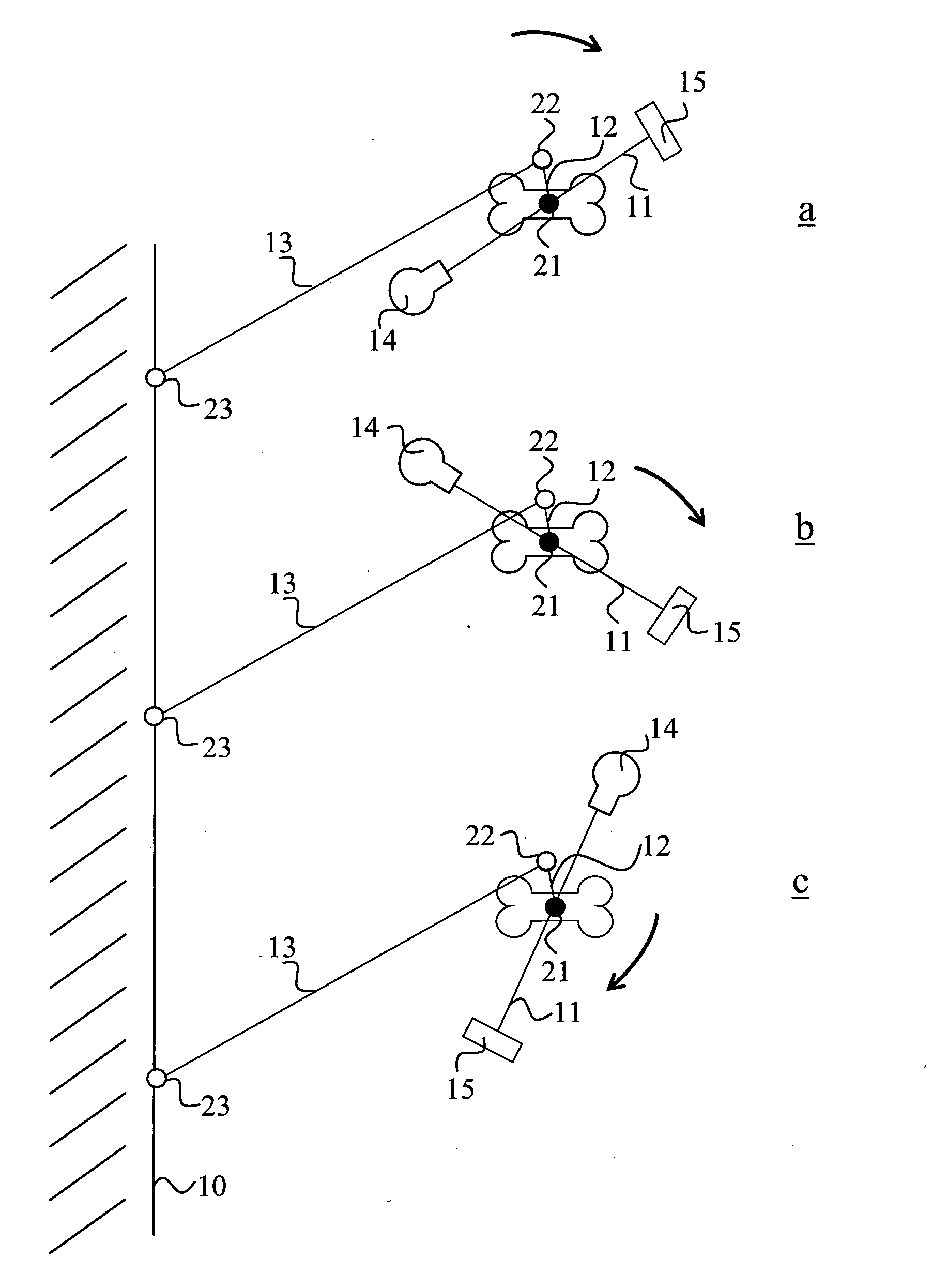
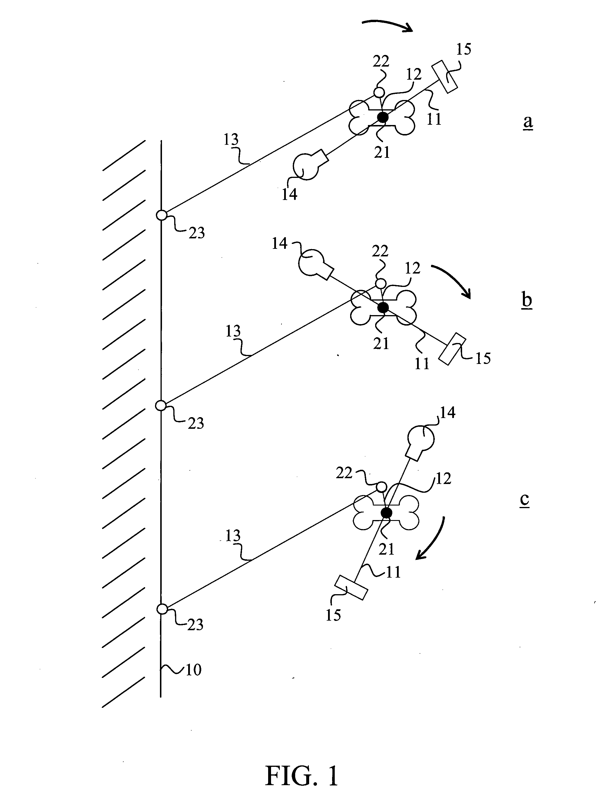
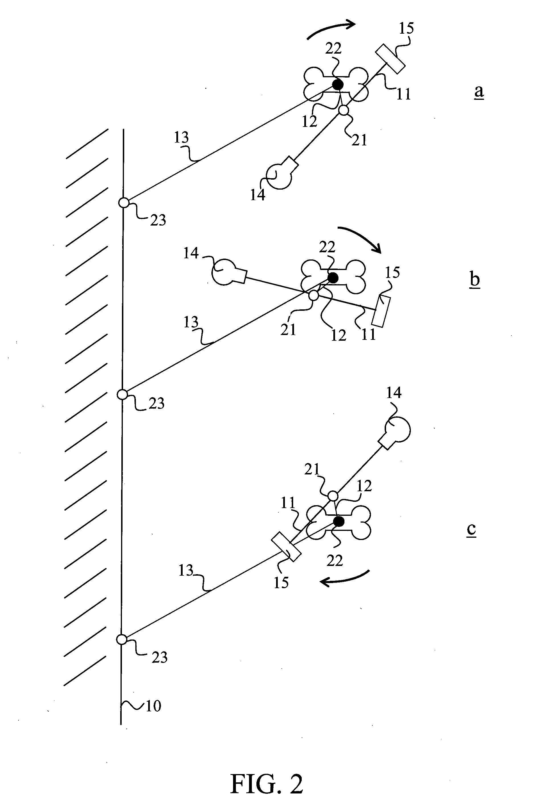
[0018]FIGS. 1a-1c show a CT imaging mode according to prior art in an apparatus which comprises a first arm part 11 comprising imaging means (a source of radiation 14 and a receiver of image information 15) and a second arm part 12 supporting said arm part 11. The first arm part 11 is arranged turnable with respect to the second arm part 12 around a first rotation axis 21 connecting said arm parts 11, 12. The source of radiation 14 and the receiver of image information 15 are arranged to the first arm part 11 at a distance from each other on opposite sides of the rotation axis 21. The apparatus includes a control system not shown in the enclosed figures and at least one actuator 31 (see FIG. 4) which is arranged to drive at least the first arm part 11 around its rotation axis 21. The arm part 12 supporting the arm part 11 supporting the imaging means 14, is further supported via a supporting arm 13 to a support structure 10.

[0019]FIGS. 1a-1c illustrate how the arm part 11 supporting...


PUM


Abstract

The invention relates to a computed tomography apparatus designed for dental use, which includes a first arm part supporting imaging means and arranged turnable by means of an actuator, and a second arm part supporting the first arm part and arranged turnable by means of an actuator. The actuators are arranged controllable such that, during the imaging process, said first arm part does not rotate but remains in its place in relation to said second arm part and said second arm part rotates about its rotation axis.

Description

FIELD OF INVENTION[0001]This invention relates to a computed tomography apparatus designed for dental use, especially to an arrangement for controlling motions of an arm construction of the imaging apparatus during an imaging process.BACKGROUND OF INVENTION[0002]Medical X-ray imaging has a long history. The earliest techniques were based on transilluminating the object being imaged. In transillumination, all the anatomies of the volume being imaged possibly overlapping in the direction of radiation are imaged on film on top of each other. Concerning layer imaging, i.e. a so-called tomographic imaging, on the other hand, one may get in the image being formed a desired layer of the object to become imaged more clearly by causing blurring of the other layers of the object. Depending on the imaging procedure, blurring is accomplished by changing the relative position of the imaging means and the object in a controlled manner during the imaging event either during irradiation or between ...

Claims


Application Information

Patent Timeline
Patent Type & Authority Applications(United States)
IPC IPC(8): A61B6/03A61B6/51
CPCA61B6/4441A61B6/14A61B6/51A61B6/03A61B6/4405
Inventor MULLER, TIMO
Owner MULLER TIMO
Learn More